~ RIAA–2 Configuration Calculator ~
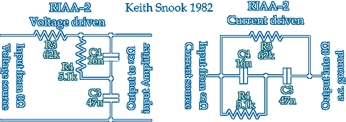
Calculates the component values to make a passive 'all in one' or 'lumped' RIAA [or other] replay equalisation [EQ] network of my type RIAA-2 as shown in this pdf and the schematic below ~ The RIAA replay characteristic is defined by 3 time constants which relate to 3 frequencies at which the amplified response changes ~ There are 2 poles T1 & T3 where gain falls with frequency at 6dB/octave and a zero T2 where gain rises 6dB/octave
The T2 zero around 1kHz provides a region of flat amplitude and phase allowing a reference point to be easily established and it reduces the gain change between 20Hz and 20kHz to 40dB rather than 60dB if only T3 were used ~ Zeros are not easy to make in practice and often a zero and pole are combined but here all 3 time contstants are established in a single block or lump
Correct replay equalisation is only obtained with correct source and load suggesting 'perfect' amplifiers are required either side of the networks ~ However this voltage driven network can incorporate a resistive [no C or L] source Rs if R3 is reduced by Rs ~ Any resistive load RL across the output will appear in parallel with Rs+R3 so R3 can be increased to accommodate RL
An adjustment of R3 alone will correct for both Rs and RL and is often required in practice ~ After obtaining initial values of R4 C3 and C4 from your chosen value for R3 you can select a standard value for C3 or C4 or maybe both rather than making non standard Cs ~ The default values here are more than accurate enough when R3 is adjusted for Rs and RL
 The 2 terminal or current driven networks are often used in negative feedback loops and have been for many years long before transistors and op-amps because when driven from a lowish output impedance and terminated into a resistive load RL the current through the network has an inverse RIAA or RIAA record characteristic
The rising current with with frequency develops a voltage across RL which could be a cathode [or emitter] load or part of an op-amp feedback loop and reduces the gain of the amplifier in accordance with the RIAA or BS1928 ~ Depending on the quality of the amplifier and the feedback topology used you may get acceptable playback of vinyl records
I refer to the 2 terminal networks as current driven because that is how I often use them ~ Not in a feedback loop around a voltage amplifier but as the output load of a Transconductance amplifier which may be the collector of a transistor with un-bypassed emitter resistor or the anode circuit of Cascode or Pentode where the current develops the equalised output voltage across the network As shown here ΐ
![[keith-snook.info]](/stuff/keith-info.png)


