![[keith-snook.info]](/stuff/keith-info-S.png)
~ QUAD II Amplifiers Modifying & Modernising ~
The 'Grey Pair' from my 1992 website now get fitted with larger PSU capacitors but damage to one of the chokes leads to further work including separate bias resistors for each KT66 as used in my 1993 mod to the 'black pair' and new valve bases plus a complete rewire with silver plated PTFE insulated wire which may not look tidy but is better suited to this application
Download a pdf of the original QUAD II schematic

The input end of the the 'Grey' QUAD IIs ~ An insulated tufnol [ SRBP ] plate about 3mm thick was cut to fit inside the chassis held in place with M4 black button head hex bolts
The concordant restoration on this site had a similar tufnol plate which was glued with epoxy for a clean finish and also filled the holes
Here the holes for the original speaker output connectors were filled with solder and rubbed flat ~ All external bolts including the KT66 sub chassis were changed to metric M4 or M3 hex button head with black finish
The sub–chassis holding the KT66s was re–tapped to M4 which works for 4BA if the depth of thread is enough ~ The transformers were fitted with the original BA bolts and only the input and and output connectors were left at this end ~ The mains connector is now sensibly located at the other end near the mains transformer in place of the voltage selector


An alternative way to mount speaker sockets in place of the mains sockets ~ I did this for some around 1980–83 but having spare mains sockets proved useful so the tufnol plate shown above is often used
Remove the two plug posts and drill the holes in the insulation to fit 4mm posts ~ If the new posts have large heads like those shown they have to be fitted after the frame has been re-fitted to the chassis

The other end of the grey QUAD11 fitted with a new safer IEC–6A mains socket in place of the voltage selector
The grey textured finish was obtained by first spraying with black Hammerite and then silver grey Hammerite from a distance so that the paint 'dust' fell onto the black and merged to give a mid grey ~ It requires a bit of practice to get the finish uniform across all amplifier parts

Building the new PSU section in the empty chassis to test the 60µF+60µF capacitor and mains transformer on load before proceeding with the rest of the rebuild
This is how a new valve amp project should start but so many don't ~ working from the PSU to the input is the way to go
The chassis is is now connected to the mains earth for safety ~ The 0V of the supply connects to chassis via a 10Ω resistor and a 47nF capacitor which can be seen bottom right below the fuse
The only changes from original for this pair were going to be bigger PSU capacitors but when I powered up the first amp PSU stage I found the previously okay choke was now open circuit ! ~ Investigation inside showed that where I had unsoldered and cleaned the tags of the choke the plastic insulation on the wire inside had melted and touched one of the studs that mount R12 and when this was wired to ground the choke fused
When a QUAD II is fully loaded with QUAD 22 pre–amp and FM and AM tuners the heavy core of the choke ~ which is not mechanically mounted like the output and Mains transformers ~ tends to drift down over the years as the tar that holds it in place melts and the internal connecting wires then rest on the backs of the tags waiting for you to resolder them one day

This neat X–ray of a QUAD II {found on the Web so please claim the credit if it's yours} shows the core of the choke 'up' where it should be touching the top of the can
It also shows that the square block capacitor houses a more traditional cylindrical can 16µF+16µF electrolytic capacitor and not a paper in oil type as some online experts claim
Luckily I had a spare good choke and also a damaged one which I had previously unwound to find the cause of failure but having spent hours trying to match the paint effect on all the parts I did not fancy doing it again for one choke so I decided to see if I could remove the core without damaging the paint
The choke was placed in a small cardboard box and put in the oven at about 150°C the tar melted and I managed to pull the core without damaging the paint then I removed the E & I pieces and washed them in white spirit to separate them and when the core had cooled down I removed the wire to see what had happened inside
It was not until the very end that I found the connection to the lead out was blown and had made a small hole in the bobbin ~ The other damaged coil had been subject to long term overload and the wire had shorted in many places ~ Should I remove the good core from my spare choke and put it in the painted case or get the two empty bobbins rewound and make two new chokes ?
The picture right shows what I decided to do ~ I contacted a number of people including Mike Davis at Woodside Electronics [ no longer trading ] because he had wound the excellent replacement output transformers that I tested for Ade Clarke of QUAD World but a 'commercial decision' led me to have Sowter Transformers fill the bobbins with a slightly thicker wire than originally used ~ The final inductance was around 29H when assembled with a 0.17mm paper shim
 The E & I pieces are NOT interleaved and the shim is required to prevent the d.c. current from saturating the core and lowering the inductance ~ Shim are also used in single ended output transformers to prevent them saturating whereas in push–pull transformers the magnetism due to the d.c. current is cancelled so the E & I pieces are interleaved for better magnetic coupling and higher inductance

The choke cases were cleaned with white spirit and the assembled cores were clamped up tight and taped and potted in electrolube polyurethane resin ~ The good core of the choke from the other grey amp was melted back into the remaining old case leaving me with two original spares and this mod with two new chokes
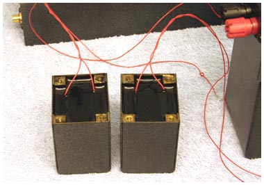
The 2 new choke cores potted in polyurethane resin which is a very good electrical and mechanical sound insulator and unlike the original Tar should remain in place over the years even as the heat rises
Note the lead out wires are PTFE supplied by me to Sowter and are long enough to wire anywhere inside the chassis if required ~ By not wiring to the tags on the base plate of the choke these are now free to mount separate auto bias resistors for each KT66

A new choke fitted and wired directly to the smoothing capacitor using the long PTFE leads leaving the 4 studs free to mount individual 390Ω bias resistors each bypassed with a 10µF polypropylene capacitor
Because the R12/C5 networks are no longer common to both output valve cathodes they have a greater effect on the low frequency response and are now used to deliberately reduce the LF response of the output stage ~ Each capacitor is in parallel [∥] with 390Ω ∥ 1/gm [KT66 =6.3e−3] ≈ 113Ω so the −3dB low frequency turnover is ≈1/(2π×C5×113)
The 10µF capacitors across the 390Ω resistors gives the output valves an open loop high pass response of −3dB @140 Hz ! which is high but with overall feedback [ see below ] becomes about −2dB @ 20Hz which the output transformer can handle reasonably well before saturating ~ Consider that your speakers may not go this low and all should be good
When one common resistor is used for both KT66 valves like R12 in the original QUAD 11 circuit and the 'push~pull' drive to their grids is well balanced [ as it should be ] then hardly any a.c. voltage will appear across R12 and hence C5 actually passes very little a.c. current so unmodified C5 need only be about 22µF and making it higher will have little effect other than ...
If it is any higher than say 47µF it could allow any low frequency imbalance current to saturate the output transformer ~ Making C5 higher than 100µF as some other QUADII modification sites advocate could be done but the low frequency response at the input should be tailored to about –3dB @ 30Hz ~ You cannot get more out of the little SPEC 1003A transformer than it is designed for ~ You need a better transformer
If separate bias resistors and capacitors for each KT66 were not used then I would have tailored the input low frequency response by making R1 100kΩ and placing a series capacitor of 56nF between the input connector and R1 ~ If you want to evaluate separate bias resistors and bypass capacitor options try this mod
These amplifiers were intended to be driven by a low output impedance pre–amp not by a QUAD 22 control Unit so the 100kΩ input impedance was chosen ~ The input capacitor is a polystyrene type which should not upset even the most discerning golden ears ~ Especially if you don't tell them it's there
Because the separate R12a/C5a and R12b/C5b do affect the low frequency response of their respective valves the CR time constants should be matched and in this respect polypropylene capacitors 10% or better are a good choice especially as modern ones will be much better than the rated 10% ~ Also separate bias resistors are far more forgiving of unbalanced valves and individual valve faults so your output transformer has more chance of a longer life
A tag board as fitted in an original QUAD II power amp
It would have been nice to use the old carbon resistors and paper capacitors but KT66 valves and Output transformers and even EF86s are getting harder to find and more expensive as time goes by so losing an output valve or transformer due to a coupling capacitor or resistor failure is not worthwhile
It is better to listen to clear music rather than the inadequacies of aged and failing electronic components although there is anecdotal evidence that the noise from old carbon resistors and the distortion from paper in oil capacitors is pleasant

A QUAD II tag strip with the QUAD component values fitted but using modern 0.75W high voltage resistors and a 160V extended foil polystyrene capacitor for C1 and new valve bases because unusually the original ones were showing their age and suffering from my tinkering over the years
These components along with new valve bases and better capacitor types for C2 and C3 should ensure that these amplifiers last for many more years to come and that the phase response of the pair is more coherent which is very important for good stereo imaging
A nice finishing touch that indicates a modified QUAD II is to remove the paint from the boilerplate using hot soapy water and a tooth brush
The QUAD perspex name plates are back engraved and then paint filled but they can look much better if the paint is removed and the natural reflections are allowed to show through

A perspex nameplate cleaned of its paint and catching the light ~ I have done this to almost all the QUAD IIs I have modified since 1980 and there are many with this feature in Hong Kong ~ Japan ~ Australia ~ Canada and a few in the UK and after they see this maybe more from others around the world
The intention was to build this pair to the original schematic as I do not like hacking a good amplifier ~ But the failure of the choke led to fitting the separate KT66 bias resistors which turned out to be a good move ~ Other changes or additions are outlined in summary around the picture below

The coupling capacitors C2 and C3 are mounted on the KT66 bases and clearly do not have the capacitance to ground that the metal bodied originals provided ~ This capacitance is required to level the response peak above 30kHz and is provided by the twisted Orange and Violet wires that now form a small capacitor between the anodes of the EF86 valves V1 and V2
It may not look as neat as the original laced wiring but the capacitor formed by the twisted wires is subject to the push–pull voltage swing at the anodes of V1 and V2 and so has twice the effect that a single equivalent capacitor to ground from each anode would provide ~ It also helps keep some of the loose wiring tidy[ish] and neater than some of the new 'QUAD' builds from IAG
The larger value smoothing capacitor 60µF + 60µF is also bypassed with a 4.7µF 630V polypropylene capacitor across section C6 this is mounted in the pipe clip which in turn is mounted on a long bolt of the rectifier valve base ~ This was an expensive addition but does appear to make everything sharper
At present there is no poly–cap across the EF86 supply as here the impedances are much higher compared to those across C6 ~ In future I may add a poly bypass capacitor across C4 but for now I'll listen a while as it is ~ When fitting additional large capacitors ensure they are mechanically secure ~ They may be okay for you now but transporting the amps in future could be a problem
The input is now a.c. coupled and if I had not fitted the separate KT66 bias resistors the time constant of the input C and R1 would have been chosen to make the response about −3dB @ 30—40Hz ~ With 390Ω KT66 bias resistors with only 10µF across them the input time constant needs to be bigger ~ R1 was made 100kΩ and the input capacitor is 0.68µF giving a time constant similar to the C2 / C3 coupling –3dB @ 2.3Hz
The output is now subject to overall negative feedback ~ Many people have tried to copy the QUAD II output transformer including myself but all too often unless built very close to the original way and used in the original circuit the result is an unstable amplifier but it can be done
 The QUAD II negative feedback is normally taken from only a third of the output winding [ R11 connected to P ] for the 15Ω tap using only link S–R ~ And and from half of the output winding for the 8Ω tap using links Q–R and S–T ~ Thus the feedback resistor does not need to be changed when the impedance links are changed
Being a QUAD amplifier there is most likely another reason why it is done this way and it is probably to keep the amplifier stable with load ~ Especially if the load is an ESL57 or its predecessor ~ With only part of the winding in the feedback path a low impedance cannot completely shunt the feedback and cause the amplifier to overload sooner
This is the exact opposite of the QUAD I where the feedback was taken from the 15Ω tap and when the 7Ω tap was used the unloaded section of 15Ω still provided the feedback the same as the LEAK TL series ~ There is also rumour of a small value resistor in series with part of the QUAD II output winding and having undone many of them I confirm it is so
I wanted the output taps set to 8Ω so linked S–T and Q–R but then provided overall feedback by connecting R11 directly to the output terminal ~ I also wanted the sensitivity to be increased by applying less feedback ~ With a 2k7 resistor for R11 connected to the output terminal the sensitivity was about 0.5V for 10W and with these amplifiers clipping at over 20W due to the higher HT voltage from the GZ34s and the 60µF smoothing cap this was fine
The main effect of the feedback change is a reduction in output impedance or greater damping factor if you prefer ~ When coupled with ESL57s or ESL63s there was a noticeable lack of Bass most likely due to the lower resistance drive ~ With the normal feedback the output is more current source and the apparent extended Bass could well support the argument that ~ the best amplifier to drive ESL57s is the QUAD II ~ provided it does not have its feedback modified
Distortion with less but overall feedback was actually no worse than with the normal feedback arrangement and in both cases the second harmonic is higher than the third etc. ~ The harmonic distribution is unlike a normal push pull output stage where the even harmonics are usually much lower than the odd due to transformer cancellation
The QUAD 11 distortion characteristic is more like a Single Ended amplifier than a push-pull design and this may be it's appeal to those who listen to music rather than read specifications ~ The prominent 2nd harmonics are due to an imbalance in the drive to the KT66 grids which could be reduced by varying R8 but this would have to be done for each specific pair of EF86s and would probably ruin the 'warm'. . . 'musical' . . . sound of this amplifier !
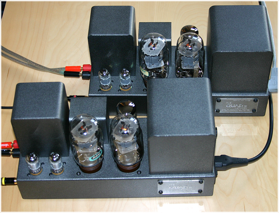
I can't "show" you how they sound but you can see what they look like in service here
![]()


" While the music played ~ you worked by candlelight "