![[keith-snook.info]](/stuff/keith-info-S.png)

~ QUAD II New Mains and Output Transformers ~
|
Some transformer manufacturers offer replacement mains transformers and chokes for the QUAD II valve amplifier but there are few that make a replacement QUAD II output transformer (OPT) and only one I know which currently (Oct 2020) makes a replacement core that fits the original case (can) and performs better than the original or the new parts fitted in the IAG "quad classic" and its modern variants |
||||||
 |
||||||
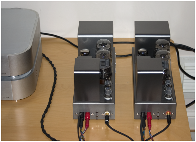
The project pictured above and described below started when I was contacted and quizzed on how a modern replacement QUAD II mains transformer should or could be fitted |
||||||
|
The owner of an early pair of QUAD IIs was concerned that a repair to his amplifiers was "not quite right" Looking at the left hand side amplifier in the picture you would probably think the same thing I had supplied replacement block capacitors to the "repairer" of these amps and I was interested to see this new mains transformer which was causing the owner some concern The transformer was made by Majestic Transformers in Poole UK and was sized to fit the original case but it had been bolted directly to the chassis as pictured because it would not fit with the mounting cheeks in place |
|
|||||
|
The 2 amplifiers pictured above are both fitted with my replacement block capacitor and other identical components including new valves ~ The amplifier with the replacement mains transformer now also had a faulty OPT which was temporarily replaced to match a pair I had just repaired for someone else so all 3 were closely matched apart from the new mains transformer and all tested and sounded similar I had previously experimented measuring the temperature rise of various QUAD mains transformers with the original and my replacement block PSU capacitors and was keen to check this replacement transformer so on top of each mains transformer there are thermocouples held in place with copper tape After several hours listening while the cores heated ~ the difference in temperature between the original and replacement mains transformers became clear ~ The new transformer was 5˚C to 10˚C lower than either of the originals ~ even with a small cardboard box over it to reduce radiated heat ~ so potting would not be a problem |
||||||
 |
The previous repairer had identified the OPT fault and two new replacements also from Majestic were supplied to me with the amps along with the old mains transformer and another new mains transformer core Considering the condition of the amps and that I had always intended to make a pair of QUAD IIs with new parts for myself ~ I agreed with the owner that I would fit the new transformer cores into the cans from his and other failed transformers and give the amplifiers a face–lift at the same time I painted my own pair |
|||||
|
The Majestic output transformer core was checked on my QUAD II test jig prior to being potted ~ Unlike the tar which these transformers were originally potted in ~ modern 2 part resins are very difficult to re–work so getting it right first time is most important when potting with these compounds Testing was done over a long period to check the temperature rise and as with the mains transformers this was lower than an original ~ These new output transformers also tested better for leakage inductance and have a higher primary inductace giving at least an octave lower frequency response |
||||||
|
With the mounting cheeks removed the mains transformer core fits neatly in the original can in the correct orientation ~ Majestic will supply the cores without mounting cheeks and with the lead–outs trimmed and tinned in the correct relative positions if you tell them you want the transformer for potting in the original case You could mount the base plate to the core using the brackets as QUAD did but I find it easier to remove the base before un-potting the old core The output transformer from Majestic also fits its can in the correct orientation ~ 90˚ to the mains transformer to prevent any stray magnetic field from it or the other channels mains transformer from coupling to the output |
 |
|||||
I was impressed with the sound of these transformers supplied by Majestic and the dedication to their customers and ordered a pair of mains and output transformers for one of my own projects which had been waiting far too long for a new pair of chokes |
||||||
 |
Having several dead chokes to hand I asked Majestic to also supply 4 bobbins wound with slightly thicker wire so a melt down in future may be avoided alhough the inductance would be a bit lower Unlike mains and output transformers a smoothing choke needs an air gap in its magnetic path to prevent the direct current from saturating the core and lowering the inductance Majestic will supply new chokes with correct air gap but because I was using the original laminations I had to make an air gap with polyester tape |
|||||
|
Re–using the original cans is a 'messy business' ~ The parts need to have all the old tar removed if the new potting compound is to be effective ~ I know others have fitted transformer cores using the brackets on the base plates and with the original tar kept in the can but this is not for me Assembly with clean parts and new cores forces an opportunity to give the cans and maybe the chassis a re-spray ~ Here the parts for my amp are spray painted with etch primer ready for the metallic coat when the bases are fitted |
 |
|||||
 |
For these amplifiers the chassis were cut to fit an IEC–6A mains plug with an integral fuse holder which fitted neatly in place of the original fuse leaving the voltage selector to connect to the taps on the mains transformers as in the original design |
|||||
|
Apart from the earthed mains connector these amplifiers were going to be essentially original apart from using my replacement tag board PCB and replacement block capacitors and point to point PTFE wiring That was the plan ~ but after a re–design of the Majestic OPT winding which allowed separate and lower resistance tertiary (cathode) windings I decided to use separate cathode bias resistors which could now be fitted from ground to each tertiary connection rather than floating between each tertiary and KT66 cathode |
|
|||||

|
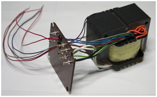
Making new SRBP base plates with the HT and KT66 connections bought out directly from the transformer through grommets meant the separate 'V' ends of the tertiary windings could be connected to ground via separate bias resistors and bypass capacitors mounted between the OPT and the choke base plate tags as shown in the picture |
|||||
|
With the KT66 connections now coming straight from the OPT in a PTFE sleeve the rest of the wiring can be done fairly neatly but I doubt it will be good enough for some on forums like DiyAudio ~ As I have done before the connections to and from C2 and C3 are twisted pairs which ensure minimum pick–up of stray voltages to the grids and provides some C for a 'pole' at the KT66 grids The cathode feedback output stage is a stable design and in most cases will not require a dominant pole for stability especially over 2 stages of gain ~ However series and parallel resonances in the transformer due to leakage inductance and winding capacitance can cause peaks and troughs in the response above about 40kHz and the correct capacitive pole 'roll off' can ensure these are no higher than 1kHz the mid band response The output connections P Q R S T have been grouped together which is why the link R—S for 15Ω output looks odd in the picture above ~ I wanted to maintain the secondary links so a change to 8Ω could be made if required but the idea of soldering links to change speaker impedance had never appealed to me and so… |
||||||
The separate bias resistors have one end connected to ground 0V so it is easy to place a switch across the other ends to enable separate or common bias resistors to be evaluated "at the flick of a switch" Using a double pole changeover with a middle 'off' position and the capacitors pictured gives 3 bias resistor options ~ 10µF||360Ω or 1000µF||10µF||360Ω separate bias and 25µF||180Ω common bias as in the original design but with polypropylene capacitors The switch used was a high quality (made in Japan RS 317–011) 6A 250V which fits neatly in one of the holes where the original output sockets were once mounted |

|
|||||
Although the switch is physically small it is well rated for the application ~ It does not "switch" the bias resistors or their parallel 10µF polypropylene capacitors ~ It only connects them in parallel and adds 4.7µF or adds the 1000µF 63V capacitors across each bias resistor and this can done without having to turn the amplifiers off or even turning the volume down
Being able to change the KT66 bias arrangement in real time without having to use a soldering iron is a nice feature and because there was a hole for another similar switch it was obvious that the speaker impedance taps should also be switched externally ~ This time I used a 4 pole change over switch and paralleled the sections to ensure a low on resistance |
||||||
 |
||||||
July 2014 ~ After listening to these amps with the orginal QUAD EF86 circuit for over a year I have now fitted the triode cascode driver circuit shown here ~ And after a few more years in 2021 I definitely prefer the cascode drive which sounds . . . ~ 2024 I am selling some of these projects to make space and finish my latest QUAD II mod |
||||||
 The open loop low frequency response with only 10µF in parallel with 360Ω is about –3dB at 60Hz which may appear a bit high ~ The calculation takes into account the shunt effect of the cathode output resistance and without it would be about 44Hz ~ The closed loop (with negtive feedback) low frequency response is about the same in all 3 positions but the reduced feedback factor at low frequency in the middle postion has an interesting effect
![]()


" Just by chance you crossed a diamond with a pearl ~ You turned it on the world "