![[keith-snook.info]](/stuff/keith-info-S.png)

~ Quad II C4 & C6 Block Capacitor Replacement ~
2026 New Design all Polypropylene Film

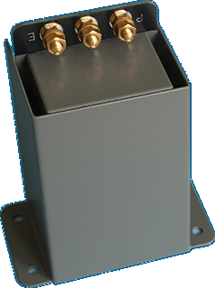
New Replacement Capacitors for the QUAD II PSU block capacitor C4 & C6 ~ Shown right are supplied in Admiralty grey painted aluminium covers to replicate the look of the original part [which varied a lot]
These drop in replacement parts fit directly in the space of the original TCC 715525 16µF + 16µF 450V capacitor without cutting or drilling or soldering and use all 4 mounting holes like the original which prevents strain on the perspex badge and they don't look out of place
Fitting is a simple DIY job requiring only a 1⁄4" or 6mm flat blade screwdriver and 4BA or M3.5 nut spinner or socket and a small 4BA or 6mm M3.5 spanner ~ To fit the replacement using the original solder lugs remove only the top brass nut and one washer from each terminal and fit the solder lugs then washers and nuts
Take care not to over-tighten the nameplate screws as the perspex plastic may crack ~ Often the chrome plated raised countersunk 4BA screws that held the block capacitor with the name plate rust and no longer look good ~ 4BA replacements are available but if you fit M3.5 which is a similar more common size you can use M3.5 nylon lock nuts and tighten the name plate just enough without the nuts coming loose over time which happens as we get older
All three connections to the capacitor should come from the QUAD II wire loom in line but also check the continuity from the terminal posts to the points marked E P and GND marked around the choke as shown in the picture below ~ If you need solder lugs to fit the new parts please let me know
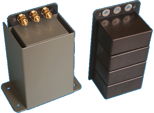
Inside the 'can' there are 4x 25uF 450V modern AVX Polypropylene [PP] Film capacitors each with 7mΩ ESR and 125˚C temperature rating ~ Configured as 2x 50µF capacitors so there is no concern about loading the GZ32 or GZ34 although in the QUADII C6 could be as high as 100uF but this all Poly-Cap replacement is more than adequate
Output power of the QUAD II amplifier may increase by fitting larger power supply capacitors with increased peak power for better bass transients ~ Hum and residual noise can improve to >100dB ~ Using these high value all polypropylene capacitors should give an improved sound reproduction from what is already a very good albeit low power valve amplifier
These replacement capacitors are sold as a pair [x2] for 140GBP plus postage at actual cost ~ April 2026
Pictured below ~ QUAD II C4–C6 replacement block capacitor and also a replacement Tag board [that I can no longer supply] update a QUAD II power amplifier giving it many more years of active service and improved performance ~ The cover of the replacement block capacitor supports the components on the PCB while providing good electrical and mechanical isolation


You may have read that there are limits to the value for C6 set by Mullard in their specification for the GZ32 ~ Most comments on this subject do not take into account that the current drawn by the QUAD II should be no more than 150mA [200mA maximum with QUAD 22 and tuners] ~ The GZ32 data is for 300mA @ 300~0~300 Vrms plus there is the impedance of the HT secondary and the reflected primary load impedance in series with each GZ32 anode
Although I was concerned about the rectifier dissipation I was more concerned about increased loading on the expensive Mains transformer but neither increases with C6 as high as 100µF and possibly greater ~ The GZ32 current waveforms have both an a.c. and d.c. component and it is the a.c. ripple current that increases as the value of C6 is increased and with only PP [no electrolytic] capacitors the d.c. leakage current is almost non existent
For many years I have fitted higher values for C6 and seen no significant increases in mains input current ~ In Europe the mains voltage can be as high as 253 Vrms and this simultaneously increases both the HT and the heater supplies which have a far greater effect reducing valve and the mains transformer life ~ Check the heater supply is not more than 6.7 Vrms and if it is change the mains taps and consider increasing the value of R12 to say 220Ω
If fitting these replacements increases the HT more than about 5% then the original block capacitor may have been faulty or there is another fault on the amplifier ~ With a good condition original C6 the there will be about 15–17 Vrms a.c. ripple on the HT supply to the KT66 anodes with no input signal ~ If higher than about 20 Vrms then C6 may be low value or the KT66s are drawing to much current which can be checked by measuring voltage across R12
 A 'leaky' C2 and or C3 will increase the KT66 current due to positive grid voltage ~ This may be seen as a larger than normal d.c. voltage across R12 ~ With the original C2 C3 or other aged paper in oil capacitors this effect may appear 'weather dependant' as it varies with humidity and temperature and with time in use again like we do as we get older
Capacitor Leakage can be checked in the amplifier by disconnecting the end of C2 or C3 that is connected to pin 5 of the KT66 base and looking for a reduction in R12 d.c. voltage but take care not to disconnect the wire to pin 5 ~ You can then measure the voltage between 0V GND and the open lead of C2 or C3 and if you know the resistance of the meter you can calculate the leakage resistance and current as show here
If you have fitted modern 'poly' capacitors for C2 and C3 or good paper in oil capacitors but still have a high voltage from each KT66 control grid pin 5 to ground it may be the KT66s are 'gassy' or the valve base is dirty ~ The voltage on each KT66 grid should be no more than about 1V when the amplifier is hot

With perfect C2 and C3 and good KT66s the voltage on the KT66 control grids should be about 0.25V with a few mV low frequency fluctuations
The KT66 grid bias resistors R7 and R9 are connected to the junction of R4 R10 and R11 rather than conventionaly to 0V as explained here
Measuring between the R4 R10 junction and each KT66 grid as shown pictured the ideal voltage should be 0V but in practice it fluctuates mV and should be not higher than about 1V
If you want to test for KT66 grid current you might just turn the amp upside down and poke around with the probes of your 10MΩ input multimeter but this will not give the full story ~ The KT66s should not be operated upside down for a long time but the grid voltage measurement ideally needs to be made over a period of several hours
Placing the QUAD II on its side raised by blocks under the transformers to keep the rectifier heat away from the work surface you can measure the KT66 grid voltages over a period of time ~ Checking that the voltage across R12 is less than 28V should also be done regularly ~ R12 greater than 30V or KT66 grids higher than 1V indicates a problem
![]()


" Bon Marché ~ As far as she can tell "