![[keith-snook.info]](/stuff/keith-info-S.png)
~ Tannoy Eaton Changes ~
Originally this page had information about QUAD 11 loudspeakers but unfortunately I no longer have anything to say about any QUAD speakers apart from why not be honest and and call them what they are which is Chinese mass produced IAG loudspeakers ~ Not classic British loudspeakers like those still made by Spendor ~ After 3 pairs over a 6 year period I finally learned to avoid them Don't buy a black pair because they will crack at the joints and fall apart if subjected to sunlight and they scuff very easily which is why you get a pair of snooker referee gloves with them ~ Mine were replaced by QUAD without question because the fault was clearly a manufacturing problem ~ for all models Remove the pedestal base and fit 4 rubber block feet over the screw holes ~ If you really want to keep the base glue it in place because it resonates The QUAD11s are not "bookshelf" speakers and require so much free space behind them to sound reasonable unless you block the ports and don't place them in corners ~ In small rooms especially rooms with low ceilings they sound best on their sides with the tweeters facing inward but this is also true of many small 2 drive unit speakers that normally have the tweeters at the top and is probably due to reflections from the ceiling being reduced So how about a few simple changes to improve the Tannoy Eaton or other badly produced British made Tannoy speakers of the late 1970s and 1980s ~ I like the 10 inch HPD295 Tannoy drivers used in the Eatons probably more than the larger 12 or 15 inch versions ~ most likely because my first exposure to them was listening to them in a studio environment ~ The drivers are very well designed and the cabinets reasonably well made but once the production department gets hold of them … |
||||||

|
Feeling a bit nostalgic in 2011 I bought a pair of Eatons on eBay after entering "a reasonable bid" which did not win the auction — I was offered a third or forth chance so decided to buy them but only after seeing them in person and testing them They looked very good condition and sounded okay with my QUAD303 and an ipod which I took along as the seller said they had no way of testing them |
|||||
After a few days listening at home it appeared that something was not quite right ~ operating the switches gave non repeatable results and when turning the controls back to a known position they sounded different to before they were move but this soon cleared after several operations as often happens with old switches |
||||||
Acoustic testing of the HPD295A drivers indicated the LF units were low distortion but one HF had a very high distortion which was also audibly noticeable at about 2kHz on a swept tone — The setup above shows my Agilent 35670A with a B&K measuring Microphone frequency sweeping the faulty HF unit With the rear plastic cover removed the voice coil of the driver can be removed by undoing the 4 bolts marked with arrows ~ By loosening the bolts the voice coil can be repositioned and this improved things but the distortion was still higher than the other driver ~ When the voice coil was removed it looked clean and undamaged but the gap in the magnet appeared to contain some debris |
 |
|||||
The pole pieces looked like they were coated with aged cadmium or zinc plating and the inside surfaces were very powdery ~ I found some hard cardboard that was a snug fit in the magnetic gap and this was cut into pieces with slopped edges and used like a 'snow plough' to clear the debris from the gap ~ Several "cleans" were made and dampening the pieces of card made the debris stick and the cleaning much easier |
||||||
 |
The HF voice coil was replaced and positioned for lowest distortion which was now almost anywhere with the 4 bolts in place ~ Both HF units measured good and very similar but I also had to take the other apart anyway and cleaned it with a cardboard 'snow plough' to remove debris in the gap Before refitting the HF unit covers I reduced the lenght of the thin wires connecting the HF voice coil to the socket as shown above ~ The excess wire probably made assembly easier but I felt less would be more Now inside I decided to look at the switches ~ which are not the best they could be ~ and measure their resistance although the switching faults had cleared since operating the controls often ~ |
|||||
|
Checking other connections I found several dry or badly soldered joints on the crossover PCBs so all solder joints were re-made ~ The inductor lead pictured above easily and cleanly pulled out of its solder joint probably due to heating from the 9W resistor which is thermally connected to its solder pad |
||||||
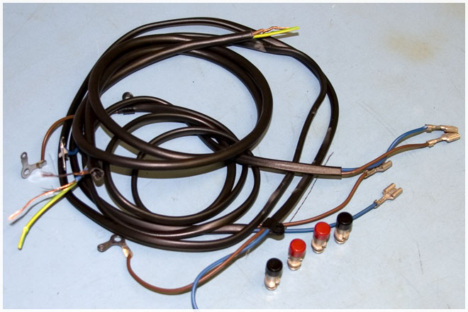
Removing the drivers had been easy because the leads from the crossovers to their 4pin plugs were over 1.2m long! ~ the cable was a lightweight 3 core mains wire which meant the HF driver had significant signal induced from the LF driver current via the resistance of their common return paths The original push terminals could not take 4mm plugs or large speaker cables so were changed for 4mm binding posts leaving me with almost 5m of cheap mains cable as shown |
 |
|||||
 |
Looking at the schematic it clearly shows separate connections from the LF and HF units direct to the negative input terminal and this is surely the way it should be wired and was most likely how it was wired as an engineering model or proto–type before the production line took over The old spade terminals were removed from the crossover PCB and short wires were soldered directly to the PCB and new terminals as shown |
|||||
Short leads would have slowed assembly and may possibly cause accidents on a production line as the driver now has to be sitting in place to fit the 4pin plug The 4 pin plugs fit better without their covers but the crossover did not fit at all well ~ The plastic front panel was distorted and had broken away from the inductor plastic bridge as can be seen in the picture above ~ The panel was straightened by heating it and glued back using plastic conduit cement |
 |
|||||
The plugs were cleaned after fitting the 4 new wires and appeared to connect to the drivers okay but the sockets are not the best and I have since seen similar with broken "fingers" where the brass has fatigued over the years ~ The LF driver wires could be soldered directly to the exposed connections near the 4 pin socket but a warning notice that this was done would be needed The repaired HF driver and the shorter separated wires made a step difference in the sound that I was not expecting or maybe it was the joints on the crossover were worse than they appeared and this is what made the speakers now sound so much better Often changes on well designed equipment do not make such a noticeable difference and when modification changes are made at the same time as rectifying genuine faults it is difficult to say what was the prominent effect but here I believe it was the interconnect wiring not fitted as intended by the designer when the product went into production |
||||||
The Eaton enclosures are made of MDF with Bitumen damping panels on the sides and back and are then lined with foam rubber "sponge" The foam lining appeared to be okay but some bitumen panels needed to be stuck down better so the foam which was glued in place had to be removed The bitumen panels were fixed using bitumen paint and while inside painting I ended up covering the entire area with a thick layer of bitumen which would help damp the enclosures better |
 |
|||||
 |
Rather than fit the old or some new foam rubber I lined the boxes with a poly?? fibre material which had come from a pair of 1960s Goodmans speakers and fitted in place with very little cutting The poly fibre was first fitted loose and later after it had proved to be a good lining material it was re–fitted using more bitumen paint although it tended to stay in place without it It is not easy to "judge" if the poly fibre wool is better than the foam but I would say the speakers with the extra bitumen damping and the poly fibre did sound better and with all the changes shown above the Tannoy Eatons sounded very good indeed |
|||||

|
||||||
Measurements and listening tests confirmed the mods to the Eatons were worthwhile and comparing them to QUAD ESL63s showed they gave a very good stereo image ~ even in my very reflective lounge ~ Yes that is a Technics SL7 above the left hand speaker and ~ No it does not because the SL7 base is so well acoustically damped |
||||||
![]()


" How they are paid in gold just to babble in the back room ~ All night and waste the time "