![[keith-snook.info]](/stuff/keith-info-S.png)

~ LEAK Hi–Fi Stuff ~
This page has some stuff about LEAK valve power amplifiers and some methods of gain reduction to make them better suited for use with modern pre–amplifiers or sources with outputs around 1Vrms or higher ~ The signal to noise of LEAK valve power amps is okay but could also be improved while lowering the gain
H. J. LEAK & Co. ltd. Brunel Road West-way Factory Estate London W3 ~ Another name in British Vintage Hi–Fi History ~ Not as innovative as the Acoustic Manufacturing Co. in my opinion ~ In the late 1950s they had 3 basic valve monoblock power amplifiers and a low power stereo amplifier ~ All based on the same schematic
All the LEAK chassis have 'acres' of free space so changing components like resistors and capacitors on the tag strips is very easy and has encouraged fitting oversized overpriced audiophoole components in an attempt to achieve some 'Audio Nirvana' that is clearly not obtainable unless other circuit changes are made
Unfortunately most suitable 'modern' replacement components for LEAK amps are smaller than the originals with short thin wire leads which look odd dangling between the tags ~ Fitting new 2W–3W metal film resistors and newer paper in oil capacitors like Amp-ohm or NOS Russian K40Y–9 can look good and will work well
All LEAK power amplifiers are very sensitive ~ The matching LEAK pre–amps were very poor in design and performance ~ their signal to noise S/N was >20dB worse than the power amps and the output was only 125mV so the power amps needed to be sensitive ~ Sell your old LEAK pre–amp and buy anything else unless you like the noise
Like The QUAD QC22 the LEAK pre–amplifiers were powered from a power amplifier via a removable umbilical cord with octal plugs and sockets ~ Unlike the QUAD which uses a series choke the LEAK HT supply from the power amp is via a high value resistor chain which also supplies HT to the 1st and driver stage valves
The voltage to the power amp first stage valve will drop greatly with a pre–amp connected and may be even lower than it should be with aged capacitors in the pre–amp ~ When using mono–block power amps where only one supplies the pre–amp the two power amplifiers may be operating with different HT conditions
The LEAK PLUS range were smaller than their original designs and used an 'Ultra Linear' output stage with grain orientated steel in the core of the transformers including the Mains Tr [unlike some modern designs] ~ The Stereo 20 and Stereo 60 were also Ultra Linear output with the better transformer core material and a triode 1st stage
Amplifier AV dBFB A0
TL 50 Plus 226× ≈47dB 26dB ≈20× 4520 × ≈73dB
TL 25 Plus 160× ≈44dB 26dB ≈20× 3200× ≈70dB
TL 12 Plus 110 × ≈41dB 26dB ≈20× 2200× ≈67dB
Stereo 20 101× ≈40dB 24dB ≈15.8× 1600× ≈64dB
The table shows the closed loop gain AV and amount of feedback FB in dB and open loop gain A0 for the 1959 LEAK power amplifier line up calculated using data from the published specifications for sensitivity and FB for the 15–16Ω output tap ~ dBFB=20log(1+βA0) where β=FB ratio
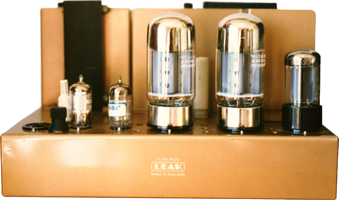
A commercial audio power amp has a sensitivity of about 0.5Vrms to 1.5Vrms for full output power so taking my chosen input of 1Vrms this translates to a gain of about 23dB for 12W into 16Ω ~ Each doubling of power requires 3dB more gain for the same input so my modified TL50 pictured above had gain reduced to 30dB from 47dB
The normal 'valve' power amp also tends to have a gain margin that is about 7-8dB and this is why I am working here in dBs ~ The manufacturer would like about 20dB or more overall feedback to lower the output impedance and keep the extremes of the frequency response 'in line' with the response around 1kHz and of course lower the THD
The amount of feedback FB in dB is the reduction in gain when feedback is applied and the gain margin is the amount by which the open loop gain A0 or the feedback FB can be increased before the amplifier becomes unstable ~ The 'normal' valve amplifier is class A or AB and A0 will be about 6dB higher without a load on the output transformer
The LEAK power amplifiers are about as normal as they come and we can assume that A0 and FB have been maximised for the valve line–up used and that increasing FB by 17dB as required for my 1Vrms input TL50 is likely to cause instability ~ LEAK stated that they aimed for a 10dB ±3dB gain margin and 6dB of this is to allow for open circuit operation
The easiest way to lower the gain or sensitivity of any LEAK or similar power amp is to remove the cathode bypass capacitor of the first valve ~ Removing C2L and C2R will reduce the A0 of the Stereo 20 by about 10dB and removing C2 from the TL50 will reduce A0 by about 9dB but the closed loop gain will be reduced less than 1dB
Without the first valve cathode bypass capacitors you get an improvement in linearity [lower open loop distortion] and lower noise floor [due to lower gain of the first stage] ~ These changes alone may not make the amplifier sound any different but the damping factor will be worse and the reduced negative feedback [NFB] may change the sound
Having no bypass capacitor across the cathode bias resistor there is no question of capacitor quality affecting 'the sound' at this point and this is my preferred option to reduce sensitivity even if the overall feedback still has to be increased to actually reduce the gain and to restore the low output impedance ~ Less really is More

The input valve in the LEAK configuration ~ whether a Triode or Pentode ~ will produce mainly 2nd harmonic distortion then a lower level of 3rd ~ With triodes the higher order harmonics tend to fall progressively but pentodes may produce higher odd harmonics greater than the adjacent even harmonics and detectable harmonics to higher orders
With an un–bypassed or partially bypassed cathode resistor the THD+N produced by a correctly biased single valve stage always appears to be lower than the fully bypassed or fixed bias option
Having applied the removal of the cathode resistor bypass capacitors to my own TL50s and several Stereo 20s and other valve amplifiers I was then introduced to 'evidence' that an un–bypassed Rk may actually increase the 3rd harmonic and odd order distortion of a triode but I had never noticed this during the testing of many amps
The graph above is a reproduction of Fig. 4 from a 1950s? USA article 'Which Tube Shall I Use?' by George Fletcher Cooper and is used by him to demonstrate that varying the amount of un–bypassed cathode resistor can introduce 3rd and odd harmonic distortion and I think we all agree that odd harmonics are not what we want
The problem I had with George Fletcher Cooper's [GFC] comments were they jumped in and out of reality as he uses many glib [his own words] assumptions ~ The foreword to the article states The author presents a lucid yet simplified description of the use of tube characteristic curves . . . should it perhaps say a simplified report of a Lucid dream
To arrive at his Fig. 4 graph GFC calculates values for mutual conductance gm modified by Rk ~ which I will refer to as gmk ~ using the formula 1/gmk = 1/gm + Rk(µ+1)/µ where he assumes that µ is always big enough for us to take (µ+1)/µ = 1 ~ This assumption is reasonable for an ECC81 and was used to produce the graph above
Another assumption GFC makes is that the curved gm/Vg plot of a 12AT7 at Va=170 [or any valve] he later uses to graphically demonstrate distortion can be drawn as a straight line between gm=0 at the valve 'cut off' where Vg ≈ –5V and gm=10mA/V at the point Vg=0V Let us look at Fig. 4. To make the work easier I have drawn a straight line gm . .
Thomas Roddam [TR] in the UK published similar articles in the magazine Wireless World in June 1951 and October 1952 which I think explain better the use of mutual–conductance/grid–volts curves and the calculation of amplifier distortion due to the nature of these curves but he also makes some assumptions so read with care
Because the GFC article was the first I was aware of ~ and because it specifically referred to an ECC81 amplifier stage with un–bypassed cathode resistor ~ very similar to one I was working with at the time ~ it became the focus of an investigation into just how bad a problem using an un–bypassed or partially bypassed cathode resistor was

The curve manufacturers tend to publish is that of Ia/Vg which is known as the 'mutual characteristic' ~ The differential of this curve is gm and when plotted on the same axis gives gm/Vg ~ If the Ia/Vg curve were originally a straight line the gm/Vg curve would be a horizontal line indicating that the gain gm does not vary with the input Vg
Where the Ia/Vg curve is originally 'curved' ~ as it always is to some extent ~ the gm/Vg curve may take on several forms depending on the degree and coefficients of the polynomial defining it
The graph above shows an actual curvature of gm/Vg at Rk=0Ω ~ The other curves Rk=100Ω Rk=200Ω and Rk=400Ω were calculated using 1/gmk = Rk + 1/gm taking data from the Rk=0Ω curve rather than the GFC straight line ~ The coloured lines are trend lines but even without them it is clear that as Rk increases the curve straightens
I measured values of Ia/Vg at 0.2V steps using a good Mullard ECC81 [12AT7] and calculated values of gm=ΔIa/ΔVg at –0.2V steps for a fixed anode voltage of 170V which it would appear GFC also used for his Fig. 4. ~ Readings at other anode voltages also gave curved plots which become straighter at low Vg as Va increases

At low Vg and low Ia most triodes show a very curved Ia/Vg and while calculating the gm/Vg curve for the ECC81 at Va=100V I noticed that it was very similar to the Ia/Vg curve ~ The differential of the curve was the same as the curve which makes Rk=0Ω shown on the right an 'exponential curve'
Deriving the distortion produced in un–bypassed cathode resistor amplifiers using GFC's gm/Vg straight line 'curves' does not correlate with real triode amplifier stages which tend to produce lower distortion than calculated his way
Looking at the GFC Fig. 4. graph above and comparing it with my ECC81 Va=170V graph I hope it is clear that the assumption to use a straight line gm/Vg is very misleading ~ The Rk=100Ω Rk=200Ω and Rk=400Ω curves derived from actual valve measurement [or even from published curves] always become straightened by local feedback
It looks like the Rk=400Ω curve appears to be bending downward and this should increase the 3rd harmonic but in practice a valve always generates less 3rd and odd than 2nd and even harmonics with un-bypassed Rk ~ The ratio of odd and even may change but the level of total distortion and noise is overall lower and S/N is also improved
The graphs below show harmonics to 10kHz relative to 1kHz for various values of Rk ~ The ECC81 was measured in my Amplifier/Buffer circuit with Va ≈ 90V ~ At one time I suspected the cathode follower 'buffer section' ~ which is completely un-bypassed by design may introduce extra distortion but its contribution was below –90dB
Measurements were made with the ECC81 auto-biased like the LEAK front end and many other valve amplifier stages ~ The anode load resistor RL was 130k and HT supply adjusted for Va ≈ 90V ~ The 2kΩ cathode resistor was bypassed with a 68µF capacitor with various resistors in series as listed below to get gain reduction in steps as GFC did ? without any additional overall negative feedback

The first 5 graphs above have the output set at 1Vrms by adjusting the input level ~ This is not attempting to duplicate the operating condition of any particular amplifier but is a reasonable operating point to evaluate the effect of un-bypassed Rk gain reduction ~ The output is kept the same for various input levels
The next 3 graphs have the output adjusted to 10Vrms and show the onset of overload and more harmonics start to appear but with Rk gain reduction the 2nd is lower relative to the output as Rk increases and the 3rd lower than the 2nd etc. and with this particular setup it looks like Rkof about 400Ω give best reduction with low distortion
Further investigation showed that some distortion was present at the input grid and was higher as the source impedance Rs increased as shown in the last 2 graphs ~ The previous output measurements were made with a 600Ω source impedance and would be better with a lower Rs and carefully chosen Rk
Switching between the first 5 graphs it is clear that with RL of 130k there is hardly any gain change between bypassed with 68µF and Rk 400Ω but more important the increase in odd harmonics predicted by GFC in his article are simply not seen in practice or even in theory when the input curves are measured and not assumed straight
GFC did contribute to a 1956 book on valve [or tube if you wish] design and the comment on the last page is worth noting but I cannot agree with anyone who uses techniques that only reduce only harmonics and leave the odd unpleasant harmonics prominent
When a resistive anode load is used Va will vary as Ia changes ~ As I mention elsewhere it is this 3 dimensional defining of the gain parameters that makes working with valves [or other active components] so interesting ~ If the change in gm with Va is taken into account we still see the 2nd harmonic much greater than the 3rd
With the above analysis applied to pentodes ~ as used for the first stage for the LEAK monoblock amplifiers ~ the curvature and hence 3rd harmonic distortion may be seen to be worse but again this is misleading because in practice a completely un–bypassed cathode resistor improves overall distortion and does not make the odd harmonics any worse than the even
In summary the best way to reduce the gain of the LEAK series ~ and many other 'normal' design of valve power amplifier is by removing any cathode bypass capacitor from the first stage and then increasing the amount of NFB ~ This way about 12dB [0.5Vrms for full output] of stable gain reduction can be achieved or possibly more if you are prepared to adjust the pole capacitor and can measure to confirm the stability
If you don't want to change too many things you can take the feedback from the 8Ω tap on the output transformer [OPT] where A0 is effectively 2.5dB less or from the 4Ω tap where A0 is 6dB less ~ This is similar to QUAD amplifiers where part of the OPT winding is outside the feedback loop which is more stable but not so low output impedance and with many speakers can give a relative increase in bass

The 17dB gain reduction mod required to my LEAK TL50s [c.1985] for a 1Vrms sensitivity needed a greater reduction of A0 than removing C2 alone provided
I considered changing the EF86s for triodes or connecting them as triodes to improve the S/N but I further reduced A0 by lowering the anode load resistors R5 to 100kΩ with an adjustment to R7 to lower the HT
Although the changes around the EF86 gave the required result I had also considered lowering the gain of the ECC83 cathode coupled phase splitter V2 by lowering the anode load resistors as I had done to my BBC LSM/10s ~ Due to the low value common cathode resistor the anode load resistors have to be different values to obtain a balanced push–pull output
I didn't make changes to the TL50 phase splitter but referring to similar schematics for the BBC LSM/10 and BBC LSM/8 highlighted a mistake on the LSM/8 schematic as supplied to the BBC by LEAK ~ The problem is also on the LEAK TL12 and TL10 schematics where R13 is marked as an odd value of 57KΩ when all others are E24 series
 With this calculator for the common cathode phase splitter it is easy to see that R13 in the LEAK TL12 should be 51kΩ ~ Entering values of µ=19 and ra=13kΩ for a 6SN7 triode with Va≈100V and resistor values from the TL12 schematic best balance is when R1 is made 51kΩ ~ A number 1 can often look like a 7
There are some LEAK mods which 'potential divide' the anode load of the first stage valve to reduce the gain but this method is not suitable as it does not improve the S/N or reduce the distortion ~ In fact the distortion can be worse due to over-driving the grid and having less open loop gain
Local negative feedback from un–bypassed cathode makes the cathode follow the grid allowing larger input voltage swings without producing distortion due to grid overdrive ~ If the input valve is a pentode the screen de–coupling capacitor can be connected to the cathode rather than ground to reduce pentode noise as in the TL25 and BBC valve amplifiers
 TroughLine Tuner
![]()


" Up on the hill ~ they think I'm okay ~ or so they say "