![[keith-snook.info]](/stuff/keith-info-S.png)

~HP35670A FFT Analyser USB Floppy Disk Emulator ~
It's 2020 and corona virus lock-down in the UK lets me start and even finish some long overdue projects like putting a USB Floppy Disk Drive [FDD] emulator in my trusty Agilent A35670A [HP35670A] FFT signal analyser ~ What should have been a simple fit of a Gotek emulator turned out to be more interesting due to a non standard TEAC Floppy Disk Drive fitted in the A35670A
Several years ago I managed to get the 16bit Windows 2000 programs I use with the A35670A analyser to run in 64bit windoze 10 using Wine and retired an old desktop that had a floppy drive ~ I then stored A35670A files in the analyser and down-loaded them via a USB GPIB lead but the analyser still needed to connect to a PC via a USB cable
Using a USB memory stick directly on the analyser as if it were in the FDD should be a good feature but in practice getting the 'cheap' Gotek emulator to work was not that simple ~ Apart from a non standard FDD interface on my Agilent A35670A the Gotek emulator has little support and the green LED indicated nothing useful
The original HP35670A has a yellow 'plasma display' and the later A35670A face lift replaced this with a colour Liquid Crystal Display [LCD] that has a few issues but both have a floppy disk drive to save waveform data and unlock the options if you are rich enough to afford them but the options or not actually on the floppy disks and can be easily enabled

Pictured is the FDD in my A35670A which is the later Agilent version made in Malaysia [MY... serial number] with a black fronted FDD which you may have noticed in the picture has no 4pin power connector
The FDD is a TEAC model FD235HF C558 which is a special version that has a +5V power supply within the data cable rather than a separate connector as described in this advert as 'Another option'
 Versions of the HP35670A may use a standard FDD with separate power connector ~ I once had one of the first HP prototypes which was full of 'cut and strap' connections but I can not recall if the FDD had a separate power connector or not ~ it was long ago ~ If you can help please let me know

This is the Gotek floppy disk emulator fitted on the A35670A FDD carrier
The data connector is offset to the middle and further forward than the original FDD and although the ribbon cable reached from the mother board it was tight so white heat shrink was fitted over the sharp edged tab as shown and later a longer ribbon was fitted
The front top edge of the emulator was fitted with some 2mm black foam tape to close up an odd looking gap so it did not look out of place apart from the red LEDs display ~ But it needed a 5V supply and checking the pin out of the Gotek and the TEAC FD325HF C558 revealed
|
Standard Floppy Drive and Gotek interface No Connection No Connection No Connection Ground 0V Ground 0V Ground 0V Ground 0V Ground 0V Ground 0V Ground 0V Ground 0V Ground 0V Ground 0V Ground 0V Ground 0V Ground 0V Ground 0V HIGH DENSITY SENSE No Connection No Connection INDEX DRIVE SELECT 0 DRIVE SELECT 1 No connection MOTOR ON DIRECTION SELECT STEP WRITE DATA WRITE GATE TRACK 00 WRITE PROTECT READ DATA SIDE ONE SELECT DISK CHANGE READY |
Cable PIN Number 1 3 5 7 9 11 13 15 17 19 21 23 25 27 29 31 33 2 4 6 8 10 12 14 16 18 20 22 24 26 28 30 32 34 |
HP35670A A100 Disk Drive FD325HF C558 DISK CHANGE READY SIDE ONE SELECT READ DATA WRITE PROTECT TRACK 00 WRITE GATE WRITE DATA STEP DIRECTION SELECT MOTOR ON DRV SEL N DRIVE SELECT 1 DRIVE SELECT 0 INDEX DRV SEL N MOTOR ON HIGH DENSITY SENSE Ground 0V Ground 0V Ground 0V Ground 0V Ground 0V Ground 0V Ground 0V Ground 0V Ground 0V Ground 0V DISK IN +5V +5V +5V No Connection No Connection No Connection |
The table above was derived from data for a standard FDD and sections 9–34 and 9–35 of the HP35670A service guide ~ Apart from the introduction of the additional connections marked in Magenta the difference between the FD325HF C558 A100 Disk Drive and the Gotek standard FDD pin out is simply a reversal of the 34pin connector
 The table also shows that the AT35670A A100 FDD +5V supply and an additional DISK IN line are via wires used for the Ground connections on a standard FDD ~ As all grounds on a standard FDD and the Gotek are connected together this would short the +5V if these devices were fitted in a 35670A without being modified
The DISK IN line is used by the system to detect when the A100 FDD is ready with a disk and pin22 [pin13] on the FD325HF C558 is ground so no need to do anything ~ DRV SEL N pin29 needs to be grounded for the system to use the A100 FDD as INT: disk so solder a link from P1 pin14 to ground on the Gotek PCB

The Gotek does not have a keyed connector to determine the orientation of the 34 pin ribbon cable
There is a cut out in the housing to indicate which way up the cable should go but it does not prevent a ribbon cable being inserted 180˚ upside down
As seen in the first picture above the 34 pin ribbon cable to the A100 Disk in the AT35670A is reversed with pin 1 [Red] on the right so no twist is required to connect to the Gotek
All that is needed is to hack the Gotek to provide +5V from the 34 pin cable to the PCB ~ Pins 7 and 9 and 11 need to be isolated from ground on both sides of the PCB and connected to pin1 on the adjacent P2 connector pad
Another option would be to make a custom ribbon cable with 3 wires taken out to a 4pin power connector but where's the fun in that? ~ Or you may be able to buy an interface PCB from GLK Instruments who also have a lot of useful stuff relating to old HP and other test equipment and how to get more from them

Because the Gotek PCB P1 is a cheap pin header it is reasonably easy to remove a block of 12 pins to cut away the ground on the top of the board as shown above as well as the bottom ~ The purple wire shown connects P1 pins7 and 9 and 11 to the +5V connector P2 pin1 to power the Gotek like the A100 FDD

The green LED on the front of the Gotek did not indicate MOTOR ON and using the A35670A this was confusing as I expected it to operate in a particular way at boot sequence and when saving and copying files
The white wire shown above now connects the green LED L4 cathode to P1 pin 16 to operate it directly from the system MOTOR ON signal ~ The cathode of L4 was moved to the empty position at anode of L3 ~ R21 is not fitted so this pad is isolated

With the above modifications made the Gotek powered up and was recognised by the A35670A operating system and is seen here saving a file
The USB memory stick is 1GB which was the smallest capacity I could find ~ after formatting it by pressing the 2 black buttons while powering the analyser and 4 minutes later I had 638 floppy images which was about 637 more than I needed
If you use a 2GB or larger USB stick you can have up to 999 floppy images but whatever you do placing the USB in a PC only shows the first one as FD01 or FDISK000 ~ depending on if you format with software or in the Gotek emulator
Putting the 1GB USB stick in an Apple Mac showed the first partition as FDISK000 1.44MB formatted FAT12 and a second unnamed 996MB formatted FAT32 ~ I think this is the same for Windoze 10 now ~ I eventually found several non Gotek programs that allowed formatting and reading less disc images but these are PC programs
Even with a low number of floppy images switching between disks with the A35670A reading the catalog each time often caused errors and sometimes locked the analyser ~ Checking the waveforms and especially the read data showed the rise and fall times were slow and somewhat distorted on the leading edge
The pull–up resistors on the 35670A motherboards are 2k2 for all inputs apart from READ DATA which is 1k ~ The FDD interface specification is 'open collector sources' ~ Pull–up resistors are required at the input/receiver ends and in many cases these were 2k2 — 5k1 apart from the data lines which had 1k pull–up for 'speed'
The intermittent problem did not appear to be data corruption in either direction ~ it looked like pressing the buttons to select a different floppy image was not being registered correctly by the A35670A which attempts to read the catalog for each disk change and I found something similar on the internet along with a 'schematic' of the Gotek
Looking at the schematic it has a mod related to the buttons ~ which I did not apply ~ but what surprised me was the way the 6 'open collector' outputs were configured using Mosfet 'open sources' driven from the processor via a 74HC04 Hex inverter and the diode DID across RN5 to 'speed up' the READ DATA signal
The source lines all have 1k pull–up resistors which are not required for 'open' collectors which the devices Q1–Q6 turned out to be as they are SOT23 version of 2N2222 transistors and not Mosfets as shown ~ This explains the distorted leading edge where the transistors are being over-driven even with the series base resistors RN1–RN6
Some FDD host interfaces back in the 1980s used the 74HC04 directly ~ The Gotek transistors Q1 to Q6 invert the signal so a better solution and one which some actual FDDs used would be use a 74F07 non inverting fast open collector driver and do away with Q1 to Q6 and their associated base resistors and non required pull–up resistors

Here my A100 modified Gotek FDD has a 74F07D fitted and a lot of components removed and bypassed and the signals now have fast clean edges
A Sandisk Cruzer Fit USB stick is not much bigger than a USB plug and in 2020 the smallest storage was 8GB but now 2021 it is 16GB and no doubt as time goes by >32GB will be the smallest
I only required a single floppy disk image formatted FAT12 and although there are several programs like HxC and Flash Floppy that do this they render the rest of the memory space unusable
I did not look too deeply into how the Gotek works [or doesn't] but it appears to read any FAT12 partition that is 1st on a USB memory stick when the display is 000 ~ The partition does not need to be 1.44MB or 720kB or formatted with specific block size ~ it only needs to be the 1st partition and formatted FAT12
Prior to version 10 (1703) Windows would only read the 1st partition on a removable device whereas my oldest Apple Mac computers with USB ports would read all the partitions but neither operating system will directly read the remaining Gotek 'floppy images' without specific PC software
I was only looking to copy the small often <10kB .DAT data files from my A35670A analyser on a USB stick and open the files in the HP35639A Data Viewer where the data could be displayed off–line in various ways with accurate level and phase markers etc. ~ Although Keysight state they still support the HP35670A they have no Windows 10 software for it
As I say above Wine VDM is a program that can run old windows 2000 16bit programs like HP35639A in Windows 10 but for me a better option now is to use the Virtual Box emulator ~ which is professionally produced by Oracle ~ on a MacBook or even in Windows
With a clean install of Windows 2000 in Virtual Box I installed a lot of my old software including the HP35639A Data Viewer ~ Rather than formatting the USB sticks in the Gotek or using software specifically for FDD emulators I used the MiniTool partition wizard to create a FAT12 1st partition and a large useful exFAT 2nd partition
Experimenting with MiniTool I found it awkward to make a precise 1.44MB image or any partition with small FDD sized blocks but that didn't appear to be a problem because the A35670A was happy reading and writing to a partition as large a 128MB provided it was the 1st partition and formatted FAT12

Although the 35670A was reading large FAT12 partitions okay the Catalog was very slow and an 8MB partition was much faster than any real floppy disk and more than enough space
There is a slight issue copying single files larger than 1.44MB from the HP35670A where I guess either the operating system is trying to split the file and format the expected 'next floppy' or the Gotek software is the problem ~ If you know the answer let us know
Pictured above is the screen of my A35670A displayed on an external monitor showing the directory CATALOG of an 8MB floppy image ~ The last 4 files in the list are frequency sweeps made on a pair of modified BBC AM8/16 amplifiers ~ Each file is only 4.5kB but when the 4 channels are opened together in the old 16bit HP Data Viewer software with multiple markers it is very easy to compare the 2 amplifiers to check the crossover response
If you use a single large FAT12 FD partition you may find the Gotek in the 35670A gives a 'disk not in drive' error if you fit or change USB sticks after switch on ~ To read the FD image I hold the right button on the Gotek while changing CATALOG to ON ~ this gives a 'hardware error' followed by 'file system error' which can be ignored
After releasing the button the Gotek display will have changed up one say from 000 to 001 and needs to be returned to 000 then CATALOG ON will read the disk ~ The buttons only count up so setting 009 before holding the right button will select 000 when it's released then selecting CATALOG ON immediately shows the directory
Noise on internal source and display brightness
One of the A35670A features I use a lot is the internal source and especially the periodic chirp signal which used with a uniform window and source trigger gives very fast sweeps suitable for checking tone controls and loudspeakers
When used for other measurements the internal source is fairly noisy ~ The original HP35670A has a yellow plasma display and the later Agilent A35670A replaced this with a higher resolution Liquid Crystal Display [LCD] with a Cold Cathode Fluorescent [CCF] back light
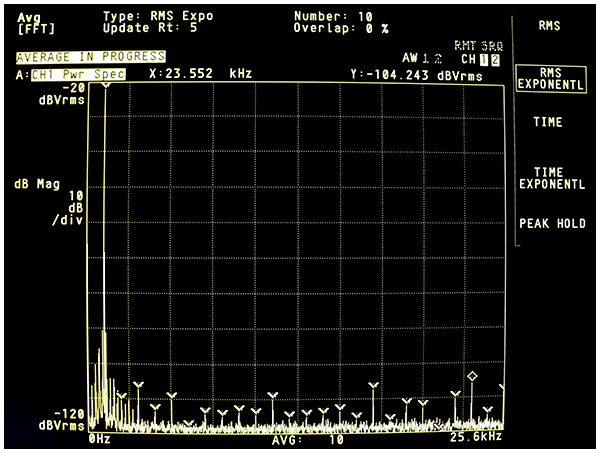
The noise seen here either side of a 1024Hz –20dBV signal is regular harmonics of a 240Hz signal ~ what is strange is their distribution around the 1024Hz source signal
Without the 240Hz the noise floor from 0Hz to the third harmonic would be about –116dBV but the harmonics of the internal source would still be about –104dBV or -84dBc due to the way the signal is derived but this better than specified in the data sheet which is –60dBc for a <30kHz sine wave output at –20dBV
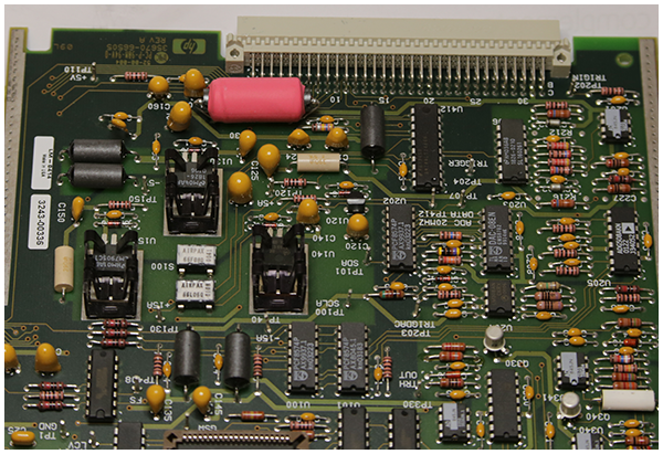
The 240Hz noise was on the CPU board A17 +5V digital supply nd this also feeds the analog board A5 and powers the digital side of a multiplying DAC for the attenuation of the digitally generated source signal ~ fitting a larger choke [pink thing pictured] to the +5V lowered the noise but it was still present on the A7 and other boards
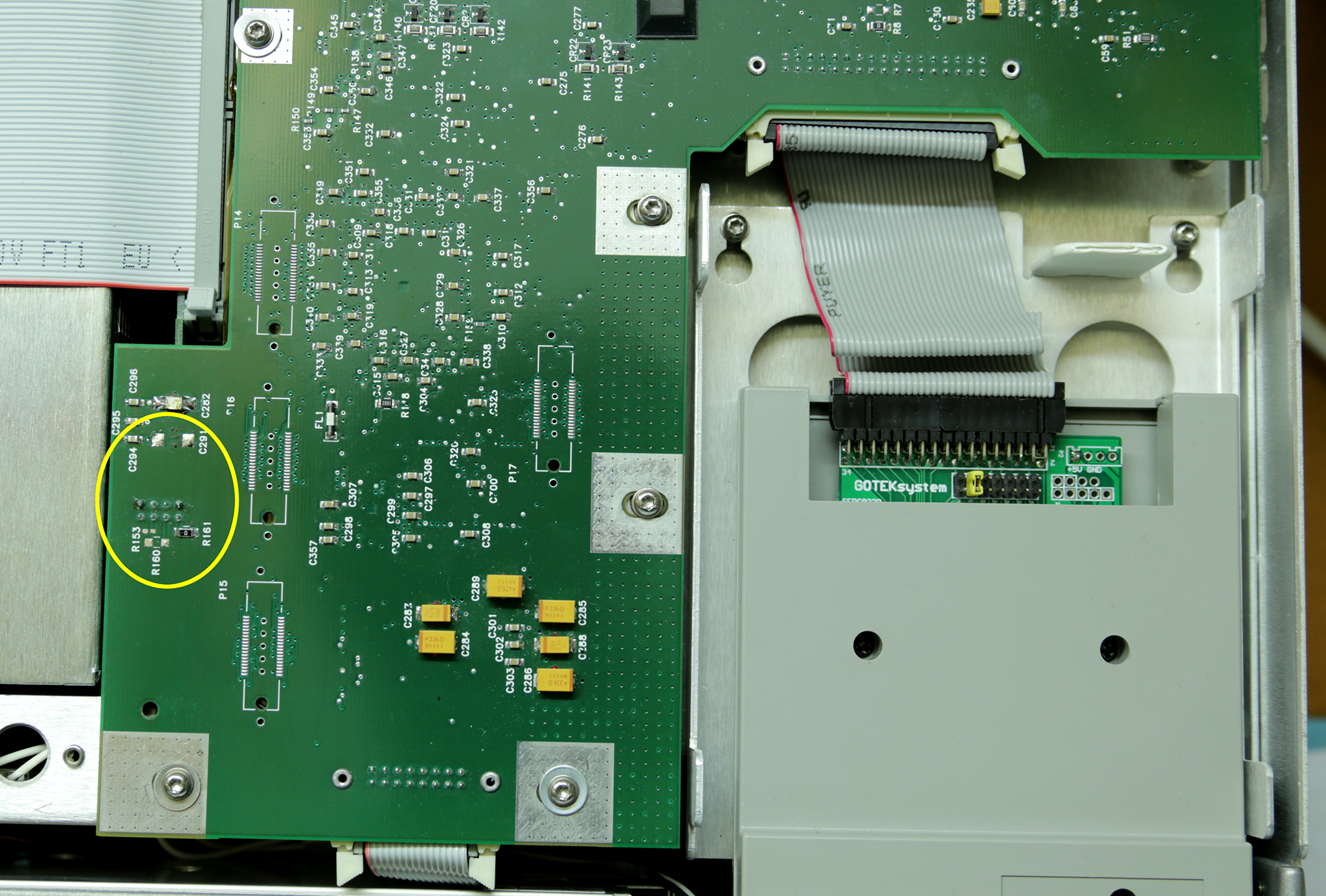
The source of the noise on the source output was from an area on the A17 board [circled yellow] which is a connector P13 supplying +5V from the digital supply to the CCF inverter below and which for some reason had spikes at 240Hz but a probe on the CCF HT leads showed oscillation at 10s of kHz as expected !
Experimenting with various capacitors to de-couple the noise led to finding a signal at 240Hz on R160 ~ The CCF backlit display had always been a bit dim and unlike the plasma display of the earlier HP35670A is not adjustable ~ Removing R160 brightened the display and the 240Hz noise harmonics disappeared
The earlier HP35670A had a separate 12V supply for the display inverter which powered the whole display [not just the back-light] and although a 200V plasma display it did not appear to cause any visible excess noise
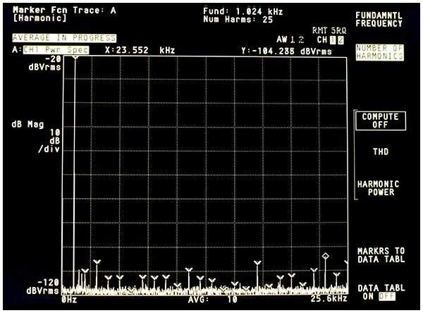
The A35670A source noise is due to the supply current to the CCF back light being 'chopped' with a 240Hz asymmetric square wave to reduce the brightness of the display
The display had always been dim and Agilent provided a viewing hood to use it in bright light ! ~ Removing R160 increases the back light but and having no noise sidebands on the source and a bright clear display has to be a good thing
The HP35670A and A35670A provide a lot of useful features once the input signal has been FFT'd into its frequency and phase information ~ Option 1D1 gives real time Octave measurements with the various octave bands derived from the linear frequency FFT displayed on a log frequency scale with each filter and total band power
Other options include Swept sine measurement 1D2 where the source and input dynamic range are adjusted to give accurate frequency responds with over 130dB dynamic range and more than 6 frequency decades with uniform points per decade [or octave] and curve fit synthesis 1D3 and arbitrary waveform source 1D4
These options cost $,$$$ and were supplied as option release keys on LIF formatted floppy disks ~ Release keys because all the software for these options is already inside the box to unlock
The serial number and firmware version along with the 'purchased' options are held in a I2C eeprom U27 in the HP35670A on board A7 and in U111 in the A35670A on board A17 and both are mounted in 8pin DIL sockets so are easy to remove and replace
As the A35670A is no longer supported plus mine now has the Gotek FDD emulator fitted the options have to be released by re-programing the eeprom which could be done via GPIB if you can get the information or by removing U111 [U27 for HP35670A] and changing a few of the 128 x 8bit characters in the 1024bit binary file
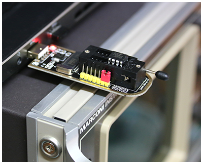
The eeprom is a 85C72 or 24C01 which can be read by most programmers including the the very cheap CH341 USB programmer shown above ~ The safest way to change the data is to read the eeprom and save then edit its .bin file and program a new eeprom ~ I used a 24C01C which is 5V only and tested several options and serial number edits
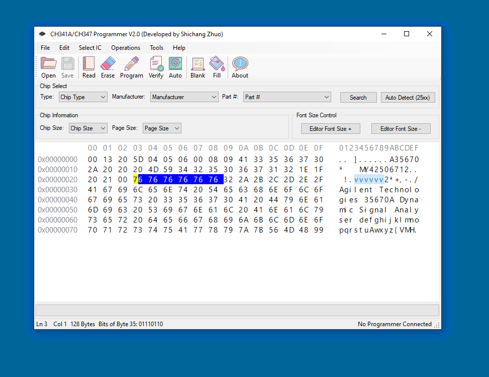
When you read the eeprom you will get a file similar to the one shown here which has been edited to release all options by putting v or 76 in the positions highlighted ~ For my A35670A this gave options 1D0 to 1D4 plus 1C2 instrument basic ~ you can also edit the serial number with say your name but try not to disturb !.vvvvvv up to /
 If you read the contents of your eeprom will you please send me a copy of the .bin file
The CH341 programmer shown above has 5V on its write line which is okay for 85C72 or 24C01C eeproms with 5V supply set by using the red link ~ Check the orientation of your eeprom with your hardware and do not follow the images on some CH341 software and some web sites
![]()


" Sharing the things we know and love ~ With those of my kind "