![[keith-snook.info]](/stuff/keith-info-S.png)

~ Classic CD Player Tweaks ~
My CD players like the rest of my audio equipment are either the very first of their type or made by QUAD before 1995 ~ I purchased the first tray loading CD player from Philips the CD104 when they were introduced in the early 80's but within a year it failed so was returned to Philips who 'fixed it' and within a few months it failed again
Philips then sent me a new one which lasted less than a year and this continued until they gave me a CD 104B which was either B because it was Black not Silver/Grey like the previous models or maybe they had ironed out the all faults and this was the improved B version
As it happened the Philips CD104B was an improved version which lasted about 2 years before finally going wrong and then I had to either get it fixed or fix it ~ By this time the Philips stock faults were becoming well known ~ Some problems with my first CD104 could be attributed in part to the mechanism but there is one design fault that plagued all the models which was through PCB rivets or bushes that did not solder well
The solder bushes are used to connect from the ground–plane of the PCBs to the other side of the boards and depending on which ones fail the player does some strange things like spinning fast and continuously or appearing to play okay but drops off the end of long CDs
There are 11 bushes on the Philips CD 104 Decoder PCB and 2 on the Servo PCB ~ The Servo PCB [the one you see when you lift the lid] also uses the leads of electrolytic capacitors to link both sides of the board and these connections are normally fine ~ The main problem area is the PCB underneath it which is the Decoder PCB

Digital end of the Philips CD104B Decoder PCB ~ The bush near the OKI RAM IC has been cleaned and re-soldered on both sides and pin 12 which connects to ground via this bush has also been soldered directly to the ground plane as have the other pins shown circled in red this is a good way to solve the problem once and for all ~ Another method shown circled in blue is to replace or parallel the bushes with a wire link
Tracks skipping may be caused by a faulty capacitor C2519 shown bottom of picture
The Control and Display PCB mounted on the front panel uses component leads to link both sides of the board and I have seen faults where the soldering has cracked causing the display not to light ~ A problem where the display does not light may be caused by C2059 on the display PCB ~ This provides the reset at switch on for the Display processor and Servo PCB

An area where faults are common but may not be obvious is the Pre–amp and Laser PCB and on some models of the CDM-1 the Hall effect motor amplifier on the CD deck
There were several versions of the C.D.M.–1 as noted in the service manual those marked with yellow labels B C H or G as pictured could have the motor PCB problem ~ Those labelled A B E or F were based on the C.D.M.–0 deck with a traditional motor driven from the main servo PCB plug 23 pins 5 & 6
From the visible side it looks like there are only a few components on these PCBs but on the other side are hidden surface mount [SMT] components that are either not soldered well or which become cracked when the PCB is flexed due to the player being dropped or the connections to the PCB sockets being pushed too hard during rework
Failure of the motor to spin correctly or the player fails to read CDs could be due to problems on the back of these PCBs ~ The motor running erratically or not at all may be due to friction and as you need to dismantle the turntable motor to get at the driver PCB this can be corrected at the same time

 I removed this deck completely as other parts were to be aligned but the motor PCB can be removed simply by removing the 2 torx bolts that hold the part [1] and undoing the nut that holds part [2] so this can be screwed off by holding the CD centre clamp from the other side after removing the white top CD clamp
The Hall switched motor PCB [3] can then be removed and the components and solder joints checked if these were suspected of causing problems such as too fast or slow running or the last tracks of CDs fail to read correctly
With the PCB [3] removed a small amount of light oil like 3in1 can be applied to the recess marked [4] ~ Leave the player or deck upside down for a long time so the oil soaks into both bearing bushes ~ A small amount of oil can be applied to the swing arm ball bearings at [5] and at head of the nut on the top side now visible with the white plastic CD top clamp removed
If impatient for a result you can remove the cir-clip from the spindle and with the deck upside down remove the spindle just enough so that the oil runs into the space between the top and bottom bearing bushes ~ Replace the spindle and cir-clip and when the player is back together working but not in use place it on one side to allow the oil the better reach the top bearing ~ Repeat this process every 20-30 years as applicable

The top CD clamp can be removed by bending only one of the support arms [B] just enough to remove it ~ I would remove the the whole top cover as outlined in the service manual but to simply oil the motor spindle removal of the top clamp may be easiest
Note there are holes [A] in the clamp arm parts to adjust the tension and level of the clamp ~ if you have good copy of Philips info on these adjustments please let me know
Failure of the laser swing arm to move to the first track of a CD on insertion or the CD jumps forward in regular hops may be due to solder connections or failure of the 33µF capacitors 2266 and 2265 outlined yellow in the picture above ~ If the motor has been oiled and PCB checked but you still have erratic motor control then suspect C 2220 outlined green above ~ The orange solid aluminium type shown here are usually good but may have failed after 30 years

Having checked the usual faults above if the player still does not work then check the power supplies ~ I'm sorry ~ of course that was the first thing you did ~ after all it's a fundamental rule of fault finding to always check the power supplies first
So the PSU tested good but you decide to change the capacitors anyway so while the PCB and Heatsink are out why not fit some better output connectors by removing the fixed audio output cable and drilling another hole above the original one ~ You will need to fit some large flanged type or insulated Phono connectors to fill the original hole

The Power supply PCB removed with its heatsink attached
New isolated phono sockets with twisted wires are prepared ready to connect to the Decoder PCB
Screened cable is not required as there is no measurable crosstalk or pick~up due to the twisted wire and twisted ~ PTFE wire in this case is so much easier and neater to work with but does it improve the sound ?
As nice and practical as they are ~ Gold plated phono sockets with PTFE insulation WILL NOT reduce or introduce any distortion ~ They WILL NOT make the Philips CD104 or ANY CD player sound cleaner or more transparent etc. ~ Those ridiculously overpriced audiophool grade cables that you bought from Russ Andrews or some other flim flam firm could now connect your CD 104 via your passive pre amp volume control but even this WILL NOT improve the CD104 sound
But This May . . .

The two TDA1540 14 bit DACs used in the Philips CD104 derive their binary weighted current sources [each one exactly half the value of the previous] for the 10 most significant bits by time division averaging
The TDA1540 data sheet states the accuracy of the current division is dependant only on the equal mark/space ratio of a series of binary divider and this process requires 'filter' capacitors which do not need to be close tolerance
The ceramic capacitors fitted to the CD104 DAC do appear to affect the sound output ~ This is possibly due to losses and or voltage coefficient of the capacitors but whatever it can be improved by use of 'better for audio' capacitors provided they are not so large they pull the tracks of the board and prevent the base being fitted
As seen on the modified Decoder PCB above the 'filter' capacitors under the DACs have been changed for SMD low loss polyphenylene sulphide [PPS] types ~ 100nF 16V and 22nF 50V which were readily available at the time in 1210 size ~ Previously I tried several types of wire ended capacitors but this was very messy even with small low voltage types ~ The 1210 size [0.012" × 0.010"] PPS fit well in place of the original 1206 size ceramic capacitors
The original surface mount components were glued to the PCB underside to enable both through hole and surface mount devices [SMD] to be soldered at the same time ~ Take care removing the ceramic SMD capacitors ~ Use hot tweezers if you can to melt the solder both ends at once and melt the glue at the same time
The Marantz CD84 made about the same time as the Philips CD104B used poly? capacitors which can be seen either side of the DACs and although it had a single sided PCB with no ground plane on it's otherwise identical decoder it did [for most people] sound much more natural than the CD104 as did following Marantz players using the Philips chipset
For years I had a CD84 and I still have an original CD104 plus 2 modified CD104s which in my opinion are the most natural sounding of them all ~ The CD84 has copper foil polystyrene capacitors for the output and de–emphasis filters and these could have an influence on its natural sound as polystyrene is an ideal dielectric for audio
Marantz was acquired by Philips in 1980 so all their CD player designs are actually Philips schematics but it was the implementation of the designs on single sided PCB and thus using leaded poly caps that may have led to the Marantz getting a much better press regarding its smoother more natural sound
Some later Marantz models used ceramic DAC capacitors as dictated by Philips but eventually they realised when the 16bit TDA1541 was introduced and was used by many more CD player manufacturers like the Revox 226 ~ B&O CD 5500 and Marantz 94 ~ Maybe there was something about poly caps for the DAC analogue stage and the Philips CD880 and DAC960 are proof that Philips also believed so ~ The DAC960 was made in Japan by Marantz and very similar to their CD94 using dipped Mylar capacitors
Unfortunately the analogue stage coupling and de–coupling capacitors tend to let the Marantz CD84 down and this was also a problem with the Philips CD104 which had 100Ω resistors in series with the op–amp supplies and ceramic 22nF de–coupling capacitors except for the +Ve supply to the Right channel NE5532N op–amp ?

Adding better analogue stage coupling and de–coupling capacitors can make a difference to the sound of the CD104 other similar players
Picture shows the analogue section of my Philips CD 104B Decoder PCB in 2002 ~ Bottom centre is the Left channel NE5532N op–amp the two 100Ω through hole resistors either side are feeding its +Ve and –Ve supplies ~ SMD 22nF ceramic de–coupling capacitors are on the other side of the PCB
In the picture centre is the Right channel op–amp which has SMD 100Ω resistors in series with its supplies but only one 22nF capacitor on its –Ve supply ?
The original 22µF de~coupling capacitors for the analogue supplies have been replaced with the 47µF tantalum bead capacitors and 4 additional 47µF tantalum beads [marked with orange dots] have been added directly between the supplies of the op–amps and the top ground plane by drilling 4 small holes in the PCB

Tantalum and solid aluminium capacitors used for the op–amp supplies and output coupling capacitors should be fine but may still benefit from being bypassed
Here 1µF 63V polyester are added across the 4 new op–amp decoupling tantalum and the solid aluminium output coupling capacitors
The sound improvement with poly bypass caps is subtle but noticeable with the DAC capacitors also been changed for poly caps
Non Over–Sampling 'downgrade'
Measuring distortion produced by a CD104 and many other CD players can be a bit worrying at first ~ The measurements fall far short of those published for THD but when you read the CD104 service manual it states use 7th order Cauer filter Philips part 4822 393 30204 to measure THD ~ IMD and S/N
Such a sharp filter is needed to remove the energy from the products around 44.1kHz ~ 88.2kHz ~ 132.3kHz etc. which make THD measurements difficult ~ The original Philips Signetics data sheet recommends a 9th order Cauer 'reconstruction filter' probably to better remove the large 44.1kHz sidebands when not using oversampling
I use both notch filter and FFT analysers to measure audio equipment and each has its merits ~ The Tektronix AA501 is a good a.c. meter with a tracking notch filter that enables viewing the analogue input signal both before and after various filters ~ Measurements of a standard CD104 with the maximum audio band passband filters are not good
Looking at the harmonics and various 44.1/n kHz frequencies from a home made AudioMaster test CD on a HP35670A FFT analyser showed the harmonic distortion in the audio band was very low [<−80dB] for full amplitude signals but even with the 4x oversampling there was some 'noise' at 44.1kHz and significant 'noise' at higher frequency

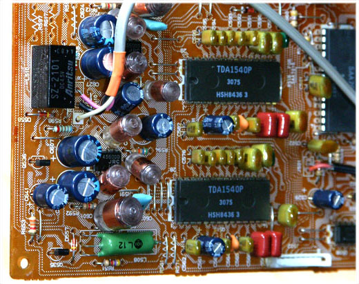
The removal of the CD104 stereo interpolating digital filter IC SAA7030 which also provides 4x oversampling is well documented on the internet
In the picture you can see 4 brown wire links between pins 3 & 20 Left Data ~ 10 & 17 Right Data ~ 7 & 21 Strobe ~ 6 & 18 Data Clock ~ where the SAA7030 has been removed and the TDA1450 DACs are now connected directly to the SAA7000 timing IC
The final part of the non oversampling change is to remove the ground 0V from pin 16 of the SAA7000 and connect it to +5V to make it output 14bit clock bursts
I had previously soldered pin 16 of the SAA7000 to the top ground plane [yellow dot top right in picture above] so this was removed and a small section of track was cut away close to pin 16 on the reverse of the PCB ~ A 1kΩ surface mount resistor was connected between pin 16 and the nearby +5V track going to pin 18
Also in the picture above ~ Green dots indicate where the ground line for the TDA1540s filter capacitors are now connected directly to the top ground plane at pin 6 and C2631 and C2581 ~ The yellow bars are where wire links forming part of the track between the DAC outputs and transimpedance amplifier [TIA] inputs have been removed and replaced with the red and white wires directly across the PCB

The 2 silver cans fitted on top of each DAC are TOKO variable inductors which are in series with the capacitors across the transimpedance amplifiers
The inductors and series capacitors form notches which can be varied in the region 25kHz to 35kHz thus reducing the 'energy' in this region which should help with the reconstruction of audio frequencies around 10kHz to 20kHz ~ That was the plan!
I tried various inductor—capacitor [LC] combinations and varied the Q of the notches and made them so they could be switched in and out to determine what effect they had on the sound of the non–oversampled TDA1540 DACs ~ Double notches gave better measured results as would be expected and the sound was I thought a bit 'smoother' while still retaining a sharp attack that was not so good with oversampling
The double notch filter switching involved several multipole changeover switches and at one point I was even considering using the switches to change between oversampling and non but I decided against that idea ~ The changes were compared against two other standard CD104s which did not have their DAC or other caps changed and the auditions often involved several bottles [shared] of red wine so not a very scientific test but I was becoming convinced that non–oversampling with even a basic LC re–construction filter was the way to go
If I were to fit an LC Cauer or elliptic filter it would need to have a controlled input and load impedance to work correctly ~ The dual notches gave good measured and subjective results so a lower order filter could be the way to go and it could be placed between the the NE5532 op–amp stages which are already part of the output chain ~ The required source and load impedances could be accurately set by series resistors
One section of each NE5532 after the TDA1540 is used as a transimpedance amplifier [TIA] which converts the DAC current into a voltage and adjusts the output high frequency response to correct for the digital filtering and provides switched de–emphasis if it were ever required
The second section of each NE5532 is a Sallen & Key style low pass filter which together with the response of the TIA form a Bessel filter to maintain a linear phase response ~ It is d.c. coupled to the TIA output and is non–inverting so both op–amp outputs only swing between 0V and about +6.8V
The TDA1540 current output will always be between 0 and about +4mA and cannot go negative so both the TIA and the Sallen and Key section op–amps are always operating in ClassA ~ This simple technique also applies to the Philips TDA1541 circuit and was systematically screwed up by Ben Duncan in his Wireless World article of May 1990 "improved CD electronics" where he put a lot of work into making the op-amp outputs work around 0V to remove the need for an output capacitor
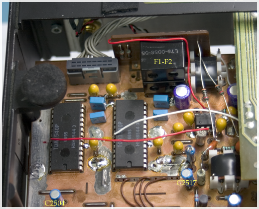
Rather than build an elliptic filter I pulled a pair of pilot tone filters from an old 1980s Kenwood stereo receiver ~ These filters are 5th order with notches at 19kHz [stereo pilot tone] and 38kHz [decoder switching frequency] ~ due to the resistance of the coils giving lower than perfect Q the filters could be adjusted with notches at about –50dB at 23kHz and –60dB at 38kHz while still having a smooth frequency [but not phase] response to about 17kHz
The filters were removed on a section of the original PCB which had ground–plane copper making it easy to solder this sub PCB to the CD104 ground–plane as marked F1–F2 in the picture above ~ The Sallen & Key components were removed and the second section of each NE5532 was used as a buffer with input resistors to ground to match the filter
The coupling was kept d.c. so the voltage from each output op–amp was about +1.7V which ensures the only series capacitors ~ new 68µF OScon ~ remain biased correctly and never get reverse current through them ~ the TIA op–amps now see a 6kΩ d.c. load and so drive a small current which can be better than driving a high impedance load or a.c. coupling especially when the output never crosses zero
TDA1540 outputs [like many DACs] are a zero–order hold staircase signal where the level of each sample is held until the next sample period ~ This gives a low pass filter effect to the output with a normalised response of sin(πx)/(πx) which has zero output at the sample frequency and multiples thereof ~ With a 4x oversampling frequency of 176.4kHz the response at 20kHz would be 20log(Sin(20π/176.4)/(20π/176.4)) = –0.18dB and even this small loss is compensated for in the CD104 by the SAA7030 digital filter and TIA / Sallen & Key filter responses
With 44.1kHz sampling frequency the loss at 20kHz is now 20log(Sin(20π/44.1]/(20π/44.1)) = –3.17dB ~ This coupled with the elliptic filter gives a response about –3dB at 16kHz which falls off rapidly whereas the original oversampled design with digital filtering is flat to 20kHz with very little phase shift ~ One slight advantage of the zero–order hold response is that the energy near the sampling frequency and its multiples is very low hence the second notch of the filter was kept at 38kHz and not moved closer to 44.1kHz
The CD104 as now configured sounds very good considering it is only 14bit NOS and has and elliptic low pass filter with less than the ideal phase response in series with the output ~ It is like listening to BBC FM radio here in the UK which has since the 1980s been distributed via 14bits [32kHz sampled] digitally companded down to a 10bits via a BBC designed system known as NICAM3 yet many listeners to the classical music station BBC Radio3 claim it is better than CD quality and live concerts are so realistic !

QUAD 66CD ~ TDA1541A
The QUAD 66CD player is based on a Philips transport and PCB which also has both through hole and surface mount components and again has surface mount ceramic capacitors for DAC filtering glued on the solder side of the PCB
Unlike the CD104 there is little room between the underside of the PCB and the base of the player so surface mount capacitors shown circled in yellow are required
In place of the 1206 ceramic capacitors 14 x 100nF 16V 1210 size PPS capacitors were fitted on their sides and 3 other 100nF PPS capacitors were fitted in place of the 22nF supply bypass capacitors
These changes to the QUAD CD66 like the CD104 changes could be subjectively evaluated as I had another unchanged CD66 to compare with ~ As with the CD104 I changed the filter capacitors first and after several months listening added the supply and output electrolytic by–pass capacitors
It appears that filter capacitors as fitted to DACs like the TDA1540 and the TDA1541 do have 'an effect' on the perceived sound and this has been noted by many others and some of the better manufacturers fitted them as standard
Better coupling and de–coupling of the post DAC audio stages of the CD 104 and CD66 also gave an improvement in my opinion but the DAC output current in each case is still converted to an output voltage via a transimpedance amplifier ~ could this be changed . . .

Bang & Olufsen Beogram 5000 series with polyester DAC capacitors

TDA1541A in Naim CD player with stacked film polyester capacitors to ground plane

One TDA1541A per channel in Marantz CD94 both with polyester DAC capacitors
~ Update 2023 ~
Most of the above work was done over a 10 year period ending around 2014 and since then I have listened to the non oversample CD104 and my original [apart from a few capacitors and RCA phono output connectors] condition CD104 several times
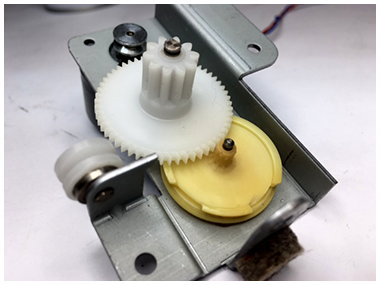
Now 2023 I have modified yet another QUAD CD66 with polyphenylene sulphide [PPS] capacitors and decided to set up the two CD104s and the QUAD 66 to review the changes but one CD104 drawer would not open and the other was erratic and noisy when opening and closing
In both cases one of the tray motor gears had lost some teeth and the gear wheel of the untouched CD104 had started to disintegrate and after opening and closing the tray several times with the lid removed I saw all of the teeth on the yellow gear break off along with parts of the edge as pictured above
I needed to find a good source of replacement gear wheels as I had done for the Philips CDM-4 and CDM-9 in the past but gears for CDM-1 were now more expensive than they should be
An ebay seller 'SiliconeMind' looked like a good choice even though the most expensive but when I started asking questions about the material used they blocked my messages
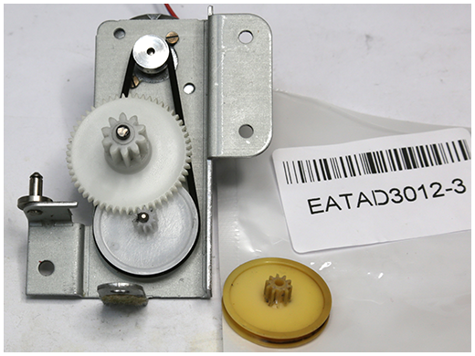
I gave up SiliconMind and decided to buy a couple of gear wheels from the cheapest Chinese supplier shown fitted ~ These parts are not made with the nice soft pliable plastic used originally but then that plastic lasted only 40 years
The Chinese parts look like they are made from a cast of an original part as the dimensions are slightly less than ideal including the size of the teeth ~ that said they are good value and do their job which is to open and close the CD Tray ~ Once closed the quality of the tray gear or drive belt has absolutely no affect on the sound of the player
As often happens with such ebay sales it was cheaper to buy the gear wheel complete with a new rubber drive belt but the belt supplied was heavier at about 1.5mm than the Philips part at 1.2mm square ~ The original thinner drive belt appeared quieter as did the original gear wheel 'originally' apart from when it hit the missing teeth and stopped
~ Update 2025 ~
After 25 Years a proper reconstruction filter
Now March 2025 I decided to revisit the idea of a better 'reconstruction filter' for the non oversampling [NOS] CD104 with the 5th order eliptic filter ~ NOS was different and possibly better than a standard CD104 with its 4× oversampling and SAA7030 noise shaping digital filter but I had always suspected a low loss high order LC filter should be better than any RC or RL filter for this modified player
As mentioned above the CD104 service manual states that performance measurements should be made using a 7th order Cauer filter Philips part 4822 393 30204 at the output but you won't have a pair of these when listening or may never see one because I can find no information about it although I guess it would be about 2kΩ input and output impedance made with capacitors and inductors to reduce the −50dBFS peaks of ripple even with 4× oversampling
My plan was to make a low impedance 11th order or higher Butterworth filter and place it at the DAC output before the output amplifiers so most of the alias noise artefacts would be reduced before passing through any active analogue stages ~ An eliptic or Cauer filter could have the same cut off for a lower order but I wanted the phase to be linear[ish] ~ Legrand and other passive filters were considered and still are
Whatever the filter topology the low impedance load on the DAC should ensure excess noise and DAC output compliance was minimum and the inductors would have low and practical values and could have high Q without being very large and awkward to fit ~ The capacitors would be 1% polystyrene paralleled to make the inevitable odd values required
The inductors I thought would need tuning or adjusting prior to fitting as aligning at least 5 even with close tolerance capacitors would not be easy
If the required odd value inductors could be found or made then the filter could be thrown together and would have the required level and phase response without tweaking
I had some 2mH inductors with only 0.33Ω resistance due to 0.35mm wire and their inductance remained constant to >100kHz and with temperature ~ They were also unlikely to saturate at 1mA
The inductors needed for a 20kHz 11th order Butterworth with 100Ω loading were 1.592mH 1.34mH and 661µH and the capacitors were ≈153nF and ≈104nF both of which could be made using 1% 51.1nF polystyrene I had and at each end 18nF was not critical
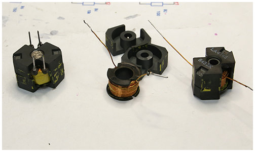
The inductors were unclipped and unwound until a value close to required was obtained within a half turn change and the ferrite air gap fine adjusted
The inductor pins often broke off so I unwound the start wire to make it longer and finished the parts as shown on the left above with the ferrite core parts super–glued together and some super–glue on the winding and bobbin to keep them stable
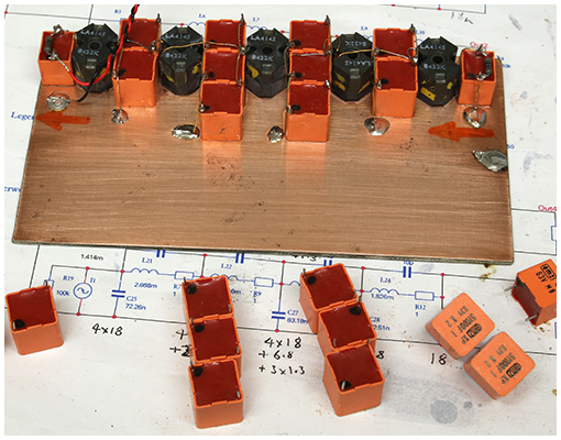
As the super–glue was to hand and I wanted a quick result the inductor coils and capacitors were glued onto a piece of single sided PCB that does not look out of place in the CD104 with its plain coper boards
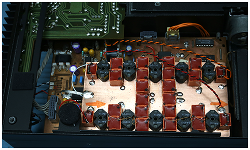
The components are similar height and the wires of the inductors join directly to the capacitors and each other and the total series resistance is <1.2Ω and the finished filter although large fits neatly over the Decoder board and is held by the base plate and some plastic foam
Using the Cauer filter I had soldered red and white wires directly from the DAC output pins 22 to the inputs of the Transimpedance Amplifiers [TIA] 6523(A) and 6525(A) ~ Now they connect to the inputs of a passive filter which has 100Ω input load and its output connected to the TIAs via 100Ω resistors paralleled with the filter output capacitors C7 shown below

The DAC output sees 100Ω Rin which acts as a current to voltage converter for the filter and the filter output sees Rout 100Ω into TIAs virtual ground so there are two current to voltage conversions producing the final output voltage ~ TIA could be replaced by Rout∥C7 to ground and a voltage amplifier but it provides amplification and Pre-emphasis as before
Pre-emphasis was used on some CD recordings but I have not seen any ~ It increases the signal level between 3kHz & 10kHz by 10dB [3.162×] then flattens out but at the expense of 10dB lower signal level below 3kHz and as music tends to have less energy above 3kHz a TIA or any amplifier before a filter will be subjected to higher alias artefacts
The CD pre–emphasis time constants are 50µs [3.18kHz] and 15µs [10.61kHz] ~ In the Philips CD104 the pre–emphasis network shown above 3572 1kΩ and 2567 15nF is switched across the TIA resistor 3574 by a reed relay ~ You can calculate various network options using this RIAA calculator setting T3 to 0 and T2 to 15µs and T1 to 50µs
Philips used additional capacitors across the TIA resistor as these formed part of the the 3rd order butterworth filter ~ With all filtering now prior to the TIA 6523(A) ~ and and the 2nd op-amp 6523(B) no longer used as an active Sallen and Key part of the butterworth filter ~ capacitor 2568 was changed to a token 47pF
With a change of TIA resistor 3574 in the schematic above to 3k the components 3572 and 2567 ideally need to be changed to 1.2857kΩ [1k3] and 11.667nF [12nF] to provide correct pre–emphasis but were left for now ~ Capacitor 2566 corrects the original 3rd order response with pre-emphasis switched so was removed
The 11th order Butterworth filter passively removes most of the 44.1kHz artefacts but unlike an active Sallen & Key found in the CD104 and many other DACs it does not 'throw them away' as heat but recombines them back into the base band ~ The sound image with a 'proper' LC reconstruction filter is amazing and clear and it is likely that many mixing engineers using DACs to monitor digital recordings never hear how good their work is
~ Still to come ~ DAC output compliance ~ QUAD 66CD modified for S/PDIF input ~ Sharper filter with more ringing
![]()


" Suddenly the music hits you ~ It's a bird in flight that just can't quit you "