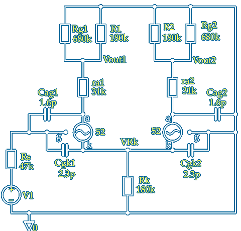
~ Cathode Coupled Amplifier Phase Splitter Calculator ~
This gain calculator is to support my QUAD II Triode driver article but can be used to calculate the gain of any cathode coupled amplifier provided µ and ra for V1 and V2 are known at their operating condition ~ Here it is shown that V1 V2 grids are connected to ground using a negative Rk supply but Rk can also be at ground and used for auto–bias with the grid resistors returned to part of Rk as seen in many designs like this or this
The calculation takes into account additional anode loads for each output due the input impedance of following stages or any bias components required which can be 'lumped' together to add to each output ~ If Rk≪R1 then R2 will need to be adjusted to obtain a balanced output so the degree of imbalance is also indicated by the calculator
Input values can be changed to calculate other parameters like the cathode follower gain of V1 reduced by R1 by making µ2 −1 ~ For calculations of triode gain and follower output impedance this may be better ~ The default values are for two sections of an ECC81 both with Ia ≈ 1mA at Va = 170V and —Vbias = 360V ~ see valve characteristics ~ Click on the image above for a pdf copy with space to make notes
 In practice with standard value components perfect balance may not be achieved or even desired because this would lead to cancellation of even harmonics leaving nasty sounding odd harmonics ~ Changing the value of R2 for balance is an iterative process ~ The gain of V1 is affected by R2 giving another value for R2 until the ratio R1/R2 is correct ~ for this reason it is important that the loading of the outputs ~ both resistive and reactive is taken into account

The three voltage gains AV1 AV2 and ARk have also been expressed as dB gains ~ This is useful if you use a meter with a dB function and relative offset ~ If the meter is 'zeroed' when connected to the phase splitter input the gain to each of these points can be easily checked to confirm the circuit and/or the valves are working correctly
I normally use PSpice modelling or just a calculator for circuit design but now that I have made these calculators I tend to use them ~ PSpice however is much quicker and more accurate for a.c. and transient analysis or when a frequency plot is required ~ Click Here for other calculators ~ Click image for PSpice plot
![[keith-snook.info]](/stuff/keith-info-xmas.png)


